F90A,B SELF-CONTAINED COMMERCIAL ELECTRONIC AIR CLEANER
68-0103-6 Revised 11-07
10
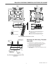
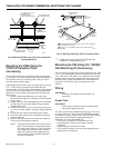
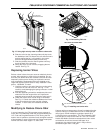
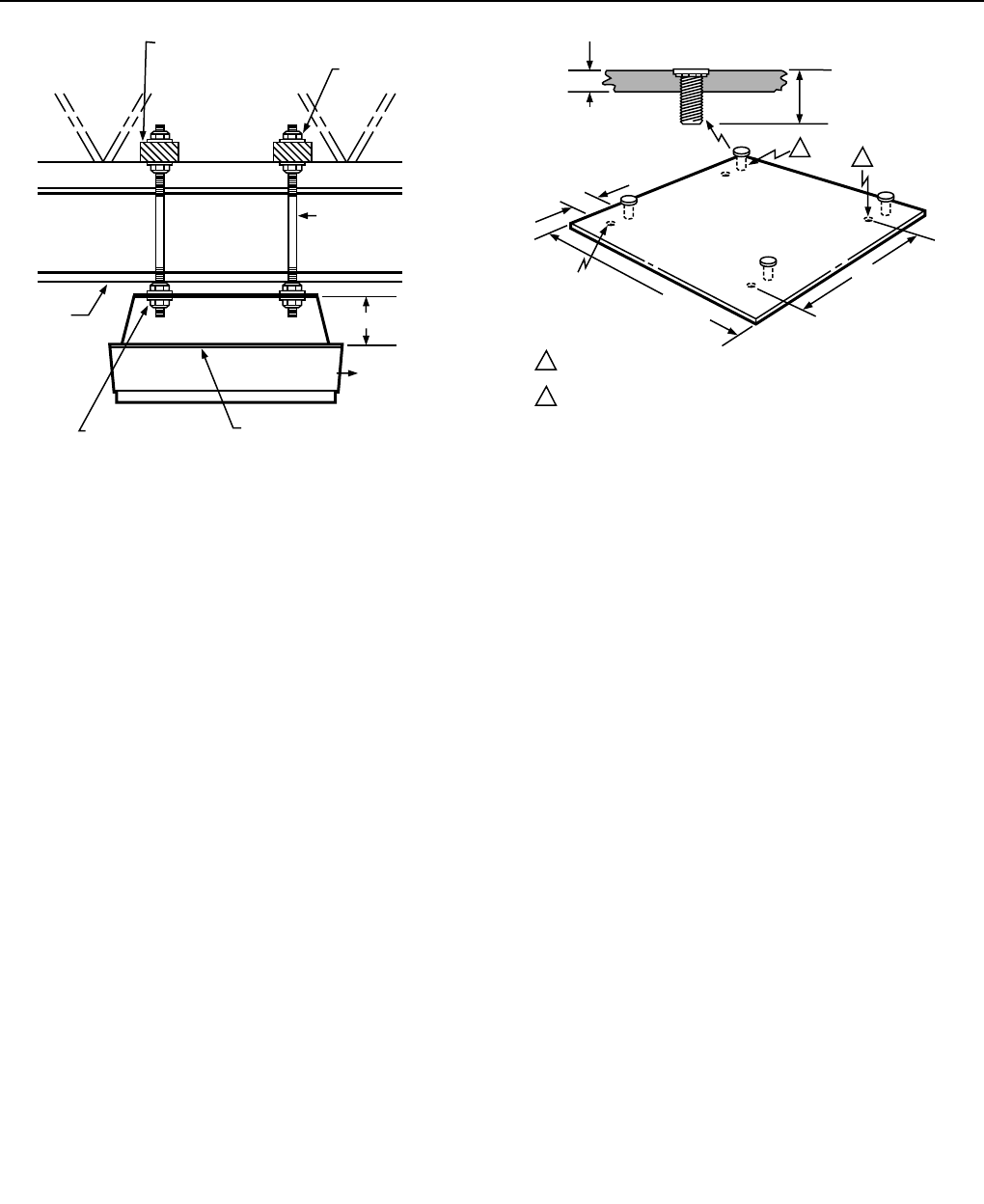
Fig. 9. Mounting the F90 using steel rods in suspended
ceiling applications.
Mounting the F90A Using the
272577A Transition Plate
(Accessory)
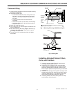
The transition plate (Fig. 10) allows the F90 to be mounted
by one person. In the two-step process, the mounting plate is
first secured directly to the ceiling joists. Then the F90 is
mounted to the transition plate.
Eight flanged locknuts (four large, four small) and four 3/8 by
3 in. (10 by 76 mm) lag screws are provided with the
transition plate. The four large locknuts adjust the F90 height,
level the F90, and provide stops for the F90 top plate (when
tightened). The four smaller locknuts secure the F90 to the
ceiling joists.
1. Screw a large height-adjusting nut on each stud.
Assure that the large nut is screwed on with its flanged
portion down.
2. Position and level the height adjusting nuts so flanges
are flush with the lag screw heads or the protruding
threaded steel rods.
3. Screw a small securing nut on each stud, leaving a 1/2
in. (13 mm) space between it and the height adjusting
nut.
4. Lift the F90 into position and locate the four studs.
5. Raise the F90 so that the four studs pass through the
keyhole openings.
6. Slide the F90 horizontally so the studs are located at
the slot end of each keyhole opening.
NOTE: As viewed from the F90 or floor side, the slot
portion of each keyhole is above the surface
of the top plate. Position the F90 so the studs
are located at the slot end of each keyhole.
When the securing nuts are tightened, they
should nest firmly in the sockets to prevent
any lateral movement.
5-1/2 (140 mm)
M1534
2 x 4 INCH (51 x 102 mm)
OR EQUIVALENT
CROSS PIECE TO
SUPPORT AIR CLEANER
VENTURI
PLATE
REMOVE
CELLS
AND
FILTERS
SUSPENDED
CEILING
1⁄4 INCH (6 mm)
DIAMETER
THREADED ROD
NUT AND WASHER
TOP AND BOTTOM
NUT AND WASHER
TOP AND BOTTOM
19 x 19 INCH
(483 X 483 mm)
1
7⁄16 INCH (11 mm) DIAMETER HOLES (4) ON 16 INCH (406 mm)
CENTERS.
2
SELF-CLINCHING PEM STUDS (4) ON 16 INCH (406 mm) CENTERS,
1-1⁄2 INCHES (38 mm) LONG.
1/16 INCH
(2 mm)
1-1/2 INCHES
(38 mm)
7/8 INCH
(22 mm)
7/16 INCH
(11 mm)
1
2
M1532
SELF-CLINCHING
PEM STUD:
16 x 16 INCH
(406 X 406 mm)
Fig. 10. Mounting F90 using 272577A Transition Plate.
7. Tighten the securing nuts until the F90 top plate
engages the height adjusting nuts.
Mounting the F90 Using the 118636C
Wall Mounting Kit (Accessory)
Two wall mounting brackets are used to support the F90. See
Fig. 11. The two brackets must be mounted on the wall with
16 in. (406 mm) for the F90A or 8 in. (203 mm) for the F90B
between centers so that the lag bolts will align with the F90
mounting holes. Fasten the brackets to the wall studs with
lag screws. On masonry walls, use appropriate screw
anchors.
Wiring
IMPORTANT
All wiring must comply with local codes and
ordinances.
Power Cord
IMPORTANT
Power supply cord must not be concealed above
the ceiling or behind the walls.
The F90, 120 Vac has a standard 3-prong plug on a 10 foot
(3 meter) power cord. There must be a standard grounded
outlet within 10 feet (3 meters) of the F90. The F90, 220/240
Vac power cord terminates in stripped leadwires for
installation of a locally purchased plug.
• Do not use an extension cord to power the F90.
• Keep the power cord out of the reach of building
occupants.
• Keep the power cord away from water.
• Do not route the power cord near sharp objects that can
damage the cord insulation.


