


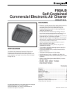

F90A,B SELF-CONTAINED COMMERCIAL ELECTRONIC AIR CLEANER
68-0103-6 Revised 11-07
7
CAUTION
Do not connect the power supply until F90 is
mounted. If the F90 is powered before an electrical
check, be extremely careful to avoid electrical shock.
Also, take care when working near the F90 moving
parts.
Unpacking
1. All F90 components are packed in one box. Slide the
F90 out of the box and remove all packaging material.
• Carefully check all F90 components when
unpacking.
• Check all packaging materials before discarding to
assure no parts or papers are lost.
• Use the mounting template marked on the outside
of the box for easy installation.
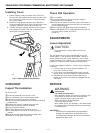
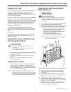
2. Pull the two latches located on the front of the F90
cover. Swing the cover down and lift to disengage from
the hinges.
3. Remove the prefilter and cell from the channel guides.
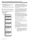
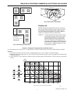
4. If installing the optional WASH LED, remove the power
supply switch plate. To install the WASH LED,
see Fig. 6.
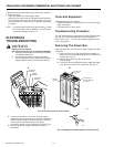
5. Remove the power box from the unit. See Electrical
Troubleshooting section for instructions.
Mounting
WARNING
Heavy Equipment.
Can cause personal injury or equipment damage.
1. If the ceiling is not reinforced properly, the weight
of the F90 could cause structural weakening and
buckling. The unit can fall, presenting a danger
to persons and equipment.
2. When using the keyhole slots for mounting,
assure the washer diameter is larger than the
keyhole diameter (3/4 in. [19 mm]) or assure the
mounting screws are secured in the small
keyhole slot.
IMPORTANT
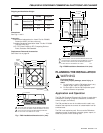
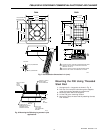
1. When mounting near walls, allow at least 16 in. (406
mm) for cell installation and removal and 15 in. (381
mm) for cover installation and removal. See Fig. 7.
2. Select a structurally strong part of the ceiling or wall
for mounting. Do not mount the F90 to a suspended
ceiling, to plaster, or to wallboard. If necessary,
construct strong framing to support the weight of
the F90.
The F90 can be mounted in any of four ways:
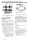
• Mounted into a ceiling joist using lag screws. See Fig. 8.
• Mounted into a suspended ceiling using threaded steel
rods. See Fig. 9.
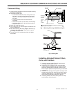
• Mounted into a ceiling joist or suspended ceiling using a
transition plate accessory. See Figs. 10 and 11.
• Mounted into a wall using the wall mounting hardware
accessory. See Fig. 12.
The F90 may also be mounted with lag bolts or threaded
steel rods reaching down to the venturi plate. However,
ensure the bolts or rods are short enough to avoid interfering
with the cells. Assure 1-1/2 threads are visible beyond the
nut.
For F90 installation dimensions, see Fig. 7.
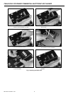
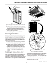
Mounting the F90 Using Lag Screws
1. Locate the ceiling joists. See Fig. 8.
2. Drill four 5/16 in. (8 mm) pilot holes in the joists using
the mounting template to locate holes.
3. Lift the F90 to the mounting location.
4. Mount the F90 using four 3/8 in. x 3 in. (10 mm x
76 mm) lag screws and washers.
NOTE: Assure the washer size is larger than the 3/4 in.
(19 mm) diameter of the keyhole or assure the
mounting screws are secured in the small keyhole
slot.