


F90A,B SELF-CONTAINED COMMERCIAL ELECTRONIC AIR CLEANER
68-0103-6 Revised 11-07
11
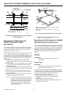
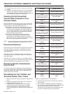
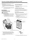
Permanent Wiring
1. Loosen the two screws and remove the plate covering
the wiring compartment.
2. Remove the power cord.
• Cut the black and white wires of the power cord,
leaving six inches from the electrical connector.
Strip 1/2 in. (12 mm) insulation from the end of
each wire.
• Cut the green wire flush with the electrical
connector.
• Remove the power cord and strain relief bushing.
• Install plug (provided) in the hole that contained
the power cord.
3. Attach the conduit to the unit.
4. Run 3-strand, no. 14 wire through the conduit into the
wiring compartment.
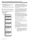
5. Wire the F90 using the wiring diagram shown in Fig.
12. Assure the green wire is secured to the green
grounding screw provided.
6. Reinstall the wiring compartment plate and tighten
the screws.
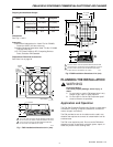
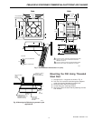
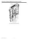
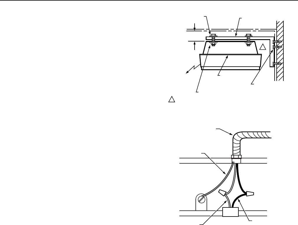
M1536
VENTURI
PLATE
MOUNT AS CLOSE
TO CEILING AS
POSSIBLE
REMOVE
CELLS
AND
FILTERS
NUT AND WASHER
BOLT AND
WASHER
WALL BRACKET
LAG SCREW
BRACKETS TO
WALL STUDS
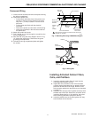
1
REPLACE REAR LOUVERS WITH BLANK PLATE ON F90 SIDE
ADJACENT TO THE WALL.
1
Fig. 11. Mounting F90 using 118638C Mounting Kit.
WHITE
FROM F90
BLACK
FROM F90
WHITE
BLACK
F90
GROUND
SCREW
GREEN
(TO GROUND)
CONDUIT
M1529
+
Fig. 12. Wiring F90.
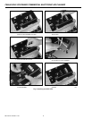
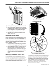
Installing Activated Carbon Filters,
Cells, and Prefilters
1. Insert the activated carbon filters (if used) into the
channel guides closest to the fan.
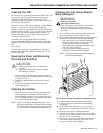
2. Inspect the cells for broken ionizer wires and bent
collector plates. Moderately bent or warped collector
plates can be bent back into shape. Broken ionizer
wires must be replaced for top efficiency as instructed
on page 15.
3. Insert the cells into the channel guides until they touch
the back stop of the F90. Assure the cell airflow arrow
is pointing toward the fan. In this position, the ionizer
wires are facing downward (away from the fan).
4. Insert the prefilters into the channel guides until they
touch the back of the channels.