


F90A,B SELF-CONTAINED COMMERCIAL ELECTRONIC AIR CLEANER
68-0103-6 Revised 11-07
16
If desired, the ozone generated by the F90 can be reduced
in one of two ways:
• Install the optional activated carbon filters.
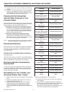
• Open the cover and move the F90 performance switch to
the LO setting. Close the cover. With the switch in LO, the
cleaning efficiency is reduced 5 to 15 percent, depending
on airflow.
NOTE: The performance switch must be set solidly in either
HI or LO position and not between, or the F90 may
not function properly. See Fig. 19.
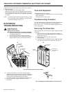
ELECTRICAL
TROUBLESHOOTING
WARNING
Electrical Shock Hazard.
Can cause personal injury or equipment damage.
1. Electrical troubleshooting must be performed by
only qualified personnel.
2. The following procedures expose hazardous
levels of electrical current. Disconnect the power
supply between checks and proceed carefully.
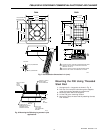
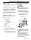
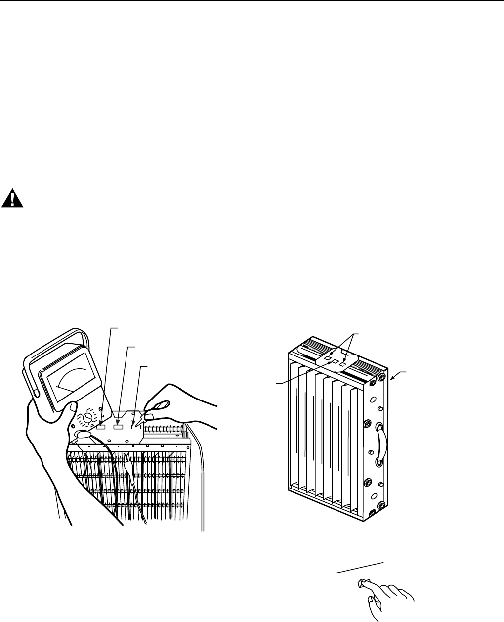
IONIZER
CONTACT
THE FRAME OF
THE CELL SERVES
AS GROUND
COLLECTOR
CONTACT
M921A
AB
COLLECTOR
TERMINAL
COLLECTOR
TERMINAL
IONIZER
TERMINAL
Tools And Equipment
Troubleshooting the F90 requires:
• Needlenose pliers for stringing ionizer wires and inserting
edge connectors.
• Test meter with 15 kVdc probe.
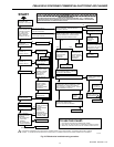
Troubleshooting Procedure
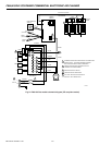
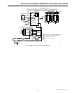
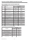
The F90 troubleshooting charts quickly isolate F90 problems.
See Fig. 20. If removing power box, follow instructions
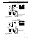
below. See Fig. 21. For the F90 schematic diagrams, see
Fig. 22 through 25.
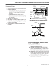
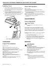
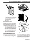
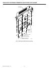
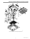
Removing The Power Box
Open the power box and remove the power supply assembly
as follows:
1. Open the cover by pulling the two latches located on
the front of the cover and swinging the cover down until
it hangs. See Fig. 13.
2. Remove the prefilter and the cell from the
channel guide.
3. Loosen the screws holding the power supply assembly
cover plate and remove the cover plate. See Fig. 21.
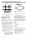
HI
LO
PERFORMANCE
SWITCH
M682
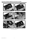
Fig. 18. Checking cells for short circuits.
3. Loosen two screws on inner wall of power supply
assembly and three screws on the top of the assembly.
Slide the power supply assembly toward the center of
the air cleaner and disconnect the two Molex
connectors and the one quick disconnect. See Fig. 21.
4. Remove the power supply assembly to a table or
workbench.
Fig. 19. Setting performance switch in either HI or LO.