


F58F COMMERCIAL DUCT MOUNTED ELECTRONIC AIR CLEANER
68-0141—4
11
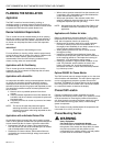
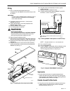
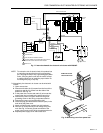
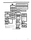
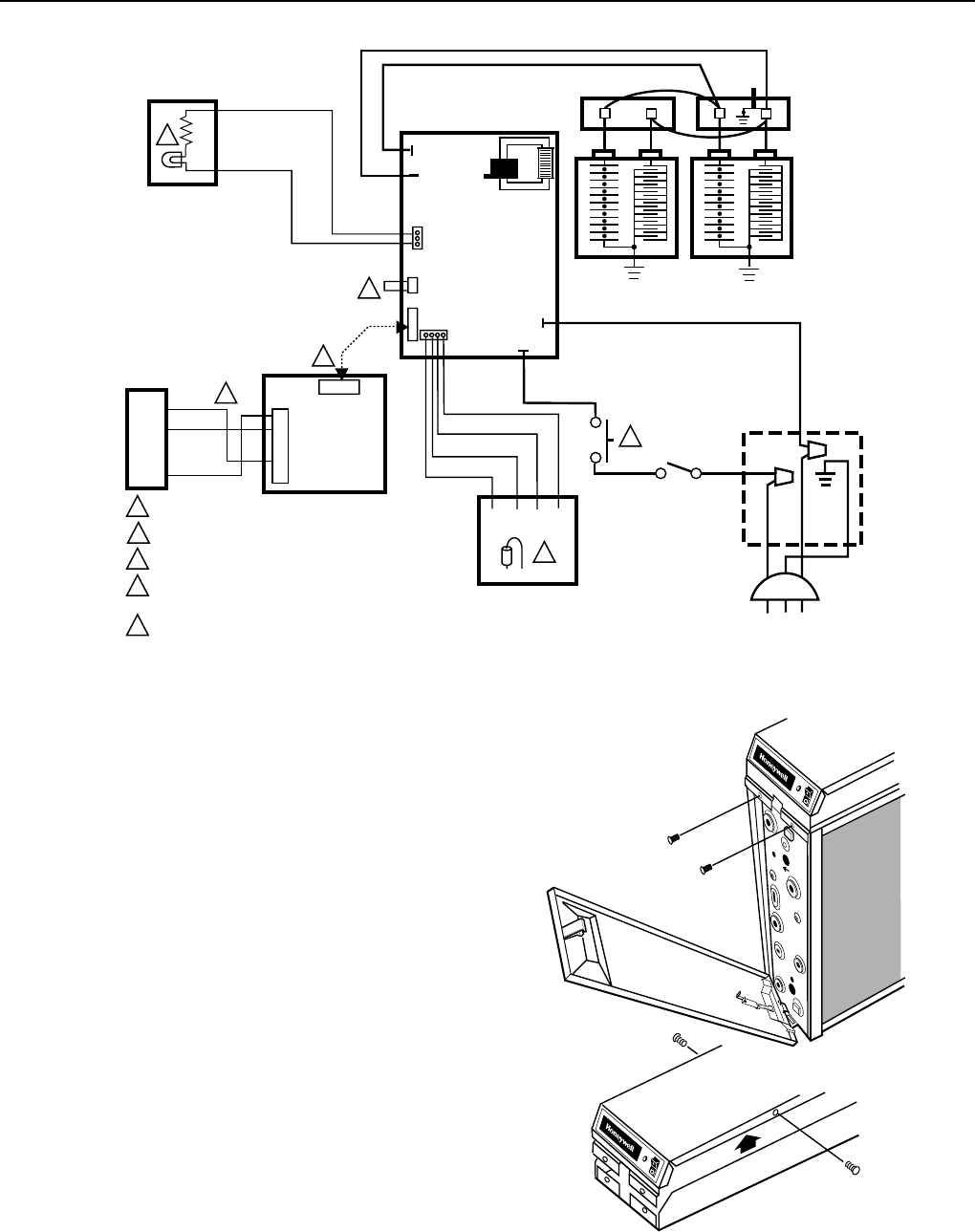
Fig. 17. Internal schematic for electronic air cleaner with W8600F.
P3
P4
P1
P2
J3
BLACK
W4 W2 W1 W3
AIRFLOW SWITCH BOARD
ORANGE
GRAY
VIOLET
BLACK
1 INTERLOCK SWITCH.
2 SHORTING BAR.
3 AIRFLOW SWITCH DISABLE JUMPER.
4 OPTIONAL W8600F AIR CLEANER MONITOR. DRIVER
BOARD AND CABLE PROVIDED WITH W8600F.
5 NEON LIGHT.
M11975
POWER
SUPPLY
2
5
BLACK
4
BLACK
BLACK
BROWN
BLACK
BLACK
WHITE
GREEN
3
1
J4
J5
J1
J1
BLACK
RED
TEST
BUTTON
CONTACT
BOARD
RED IONIZER
BLACK COLLECTOR
4
J2
B4
R3
Y2
G1
2
5
6
GREEN
RED
BLUE
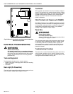
NOTE: To reduce the risk of electric shock, this product has
a grounding type plug that has a third (grounding)
pin. This plug will only fit into a grounding type power
outlet. If the plug does not fit into the outlet, contact
a qualified electrician to install the proper outlet. Do
not change the plug in any way.
❑ Alternatively, the electronic air cleaner can be wired with
conduit.
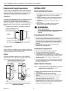
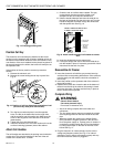
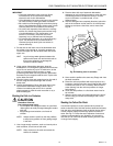
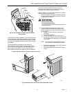
1. Open access door.
2. Remove and retain the (2) screws from the front of the
power box and the (2) screws from the sides of the
power box. See Fig. 18.
3. In the power box, remove and retain (2) wire nuts that
connect the line cord leads to the power box wiring.
4. Remove the power cord green lead from the green
grounding screw on the wiring compartment barrier.
5. Remove the power cord and the strain relief.
6. Install the plug (provided with the literature pack) in the
hole left by the power cord.
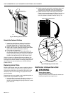
7. Attach conduit through a power box side knockout.
8. Wire the air cleaner directly to line voltage using wire
nuts. See Fig. 19. Secure ground connection to the
green ground screw on the wiring compartment barrier.
9. Replace power supply cover and access door.
M5676A
3
1
2
REMOVING COVER
FROM POWER BOX.
Fig. 18. Removing cover from power box.