


F300E ELECTRONIC AIR CLEANER
68-0240-1
12
P3
P4
P1
P2
J3
BLACK
W4 W2 W1 W3
AIRFLOW SWITCH BOARD
ORANGE
GRAY
VIOLET
BLACK
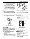
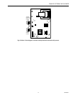
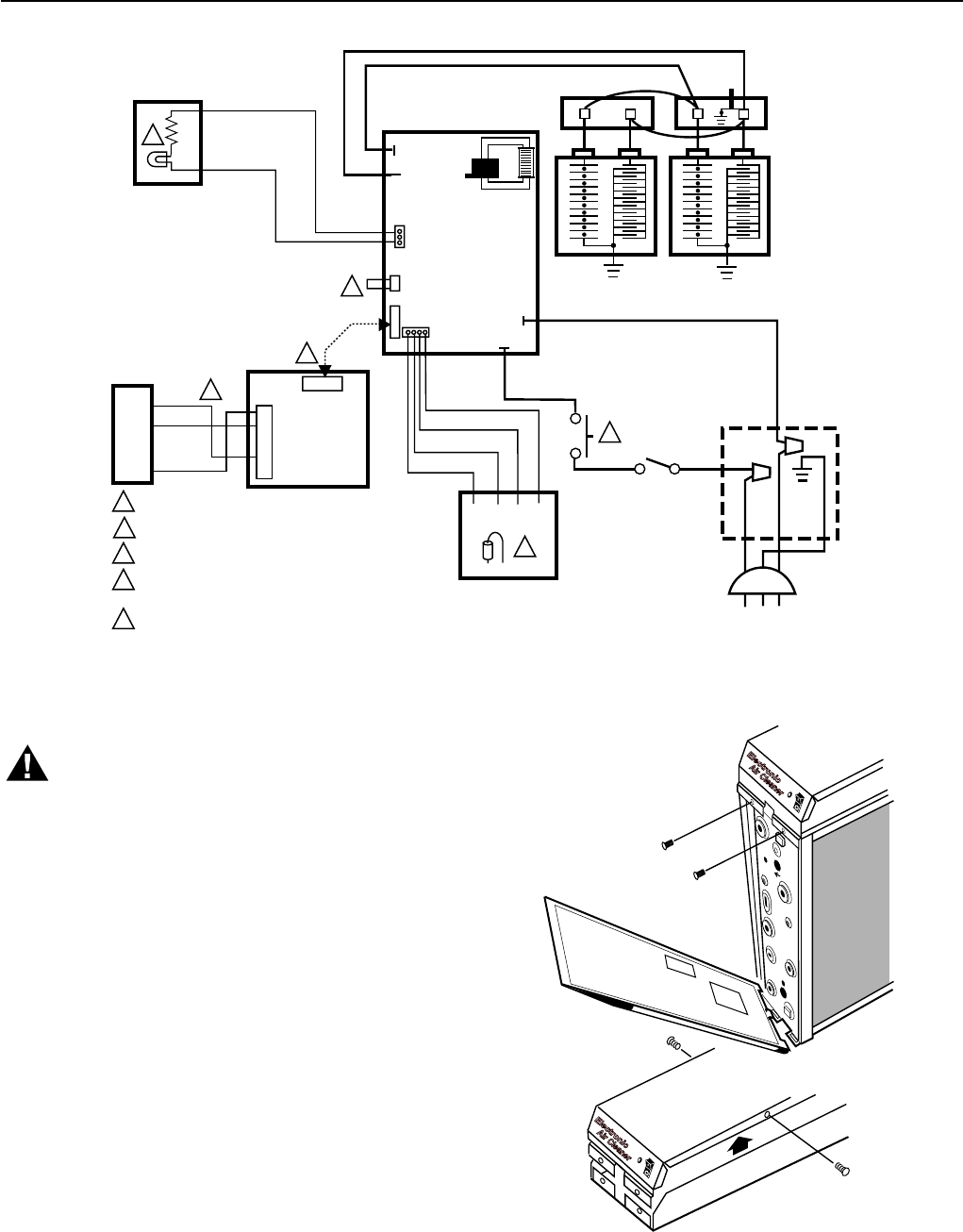
1 INTERLOCK SWITCH.
2 SHORTING BAR.
3 AIRFLOW SWITCH DISABLE JUMPER.
4 OPTIONAL W8600F AIR CLEANER MONITOR. DRIVER
BOARD AND CABLE PROVIDED WITH W8600F.
5 NEON LIGHT.
M11975
POWER
SUPPLY
2
5
BLACK
4
BLACK
BLACK
BROWN
BLACK
BLACK
WHITE
GREEN
3
1
J4
J5
J1
J1
BLACK
RED
TEST
BUTTON
CONTACT
BOARD
RED IONIZER
BLACK COLLECTOR
4
J2
B4
R3
Y2
G1
2
5
6
GREEN
RED
BLUE
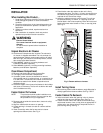
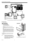
Complete Wiring
WARNING
Electric Shock Hazard.
Can cause personal injury.
Do not use an extension cord.
• Assure all wiring complies with local codes and
ordinances.
• The line voltage power source must match the voltage
and frequency printed on the label inside the access
door.
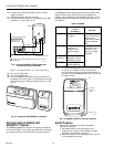
• When the system fan comes on the Air Flow Switch
(AFS) senses the negative pressure in the duct and
turns the power supply on. If power to the air cleaner is
controlled by another switch,such as a sail switch or
fan timer board, the AFS can be disabled by cutting
the jumper on the back of the AFS circuit board. See
Fig. 18.
❑ Plug the electronic air cleaner directly into the correct
voltage and frequency outlet. See Fig. 18 for internal
schematic.
NOTE: To reduce the risk of electric shock, this
product has a grounding type plug that has a
third (grounding) pin. This plug will only fit into
a grounding type power outlet. If the plug does
not fit into the outlet, contact a qualified
electrician to install the proper outlet. Do not
change the plug in any way.
Fig. 18. Internal schematic for electronic air cleaner with W8600F.
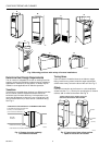
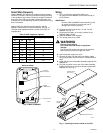
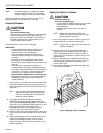
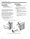
Fig. 19. Removing cover from power box.
M14738A
3
1
2
REMOVING COVER
FROM POWER BOX.