


69-1085
4
CT2700 AN ELECTRONIC ROUND
™
PROGRAMMABLE THERMOSTAT
All wiring must comply with local electrical codes and
ordinances. If unsure about household wiring procedures,
call your local heating and air conditioning contractor.
Refer to the masking tape labels you placed on wires
when you removed your old thermostat.
Match the letter of your old thermostat wire with the
terminal of the corresponding letter on your new
thermostat. Refer to Fig. 7.
M12529
ALTERNATE
MOUNTING
SCREW HOLE
MOUNTING
SCREW
HOLE
MOUNTING
SCREW HOLE
ROUTE WIRING AS
SHOWN THROUGH
ENTRANCE
HOLE
WIRING ENTRANCE HOLE
ALTERNATE MOUNTING
SCREW HOLE
W
Y
G
R
C
O
O
L
O
F
F
H
E
A
T
F
A
N
O
N
A
U
T
O
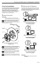
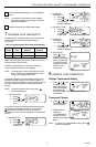
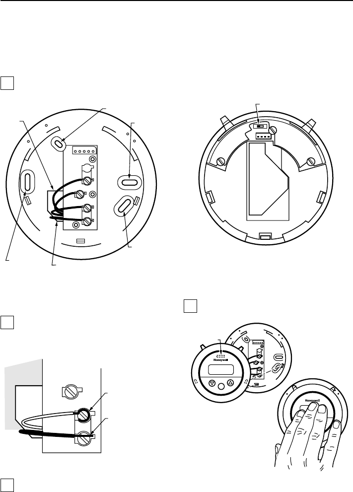
Fig. 7. CT2700 wallplate wiring connections.
NOTE: To ensure proper mounting of the thermostat,
restrict all wiring to the left side of the terminals.
Loosen the terminal screws and slip each wire
beneath its matching terminal. The shape of the
terminals permit insertion of straight or wraparound
connections. See Fig. 8. Tighten the terminals.
M12537
FOR WRAPAROUND, STRIP
7/16 INCHES (11 mm)
FOR STRAIGHT INSERTION,
STRIP 5/16 INCHES (8 mm)
Fig. 8. CT2700 methods for wiring connection.
Plug the hole in the wall with insulation to help
prevent drafts from adversely affecting thermostat
operation.
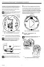
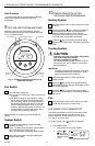
5 ADJUST FAN OPERATION SWITCH
The thermostat fan operation switch, labeled fuel switch in
Fig. 9, is set at the factory in the F (gas/oil fuel) position.
This is the correct setting for most systems. If this system
is an electric heat system, set the switch to the E (electric)
position. The E setting allows the fan to turn on immedi-
ately with the heating or cooling equipment in a system
where the G terminal is connected.
M12531
FUEL SWITCH
F
E
Fig. 9. Fuel switch, rear view of thermostat.
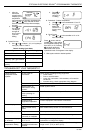
6 MOUNT THERMOSTAT TO
WALLPLATE
Align the tab and connector pins at the top of the
thermostat with the wallplate. See Fig. 10.
M12530
DASHED LINES
INDICATE TABS
ON BACK OF
THERMOSTAT
ALIGN TABS/PINS AT TOP
OF THERMOSTAT WITH
WALLPLATE CONNECTOR.
A
B
PRESS THERMOSTAT CASE
STRAIGHT ON TO LATCH.
Set
C
O
O
L
O
F
F
H
E
A
T
F
A
N
O
N
A
U
T
O
C
O
O
L
O
F
F
H
E
A
T
F
A
N
O
N
A
U
T
O
Set
Fig. 10. Mounting thermostat to wallplate.