


69-1085
2
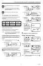
CT2700 AN ELECTRONIC ROUND
™
PROGRAMMABLE THERMOSTAT
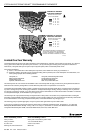
Table 1. Compatibility Chart
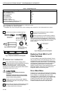
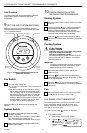
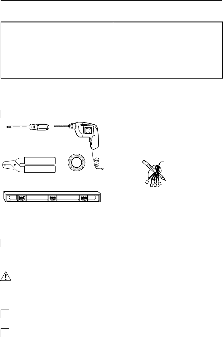
Acquire tools and items as needed. See Fig. 1.
M878B
CROSS-RECESSED
SCREWDRIVER
HAND OR POWER
DRILL WITH 3/16 INCH
DRILL BIT, IF NEEDED TO
DRILL HOLES IN WALL
WIRE CUTTER/STRIPPER OR SHARP
KNIFE, IF NEEDED TO STRIP WIRES
MASKING TAPE, IF
NEEDED TO LABEL WIRES
AS DISCONNECTED FROM
OLD THERMOSTAT
LEVEL, IF NEEDED TO LEVEL
THERMOSTAT FOR APPEARANCE
Fig. 1. Required installation tools/supplies.
2 REMOVE OLD THERMOSTAT
Test to make certain that your heating and air
conditioning systems (where applicable) are working
properly. If either does not work, contact your local
heating/air conditioning dealer. To avoid compressor
damage, do not operate the cooling system when outdoor
temperature is below 50°F (10°C).
CAUTION
Be careful when handling wires during
installation.
Damage to heating/cooling system possible.
Disconnect power at furnace or at main breaker/
fuse box before starting operation.
Carefully unpack your new thermostat, wallplate,
and decorator cover plate; save package of screws,
instructions and receipt.
Remove the cover from the old thermostat. If it does
not snap off when pulled firmly from the bottom,
check for a screw used to lock on the cover.
Loosen screws holding thermostat to subbase,
wallplate, to wall and lift away.
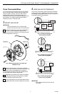
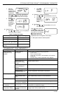
Disconnect wires from old thermostat or subbase.
As you disconnect each wire, use masking tape to
label it with the old terminal designation. If there are only
two wires, they do not need labeling. Wrap wires around a
pencil to keep them from falling back into the wall as
shown in Fig. 2.
WIRES THROUGH
WALL OPENING
M5136
Fig. 2. Wrapping wires around pencil.
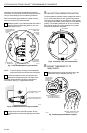
Replacing Clock With C or C1
Clock Terminals
If you are replacing a Honeywell Chronotherm® Thermo-
stat, you may find one or two wires that go to the C or C1
clock terminals on the Chronotherm®
Thermostat wiring
wallplate. Do not allow them to touch, or you can damage
your transformer. Disconnect the wires and wrap them
separately using electrical tape; do not wrap them
together. Place the wires to avoid interfering with the new
thermostat operation. Record the colors and terminal
designation labels of the remaining wires.
Six or More Wires
If there are six or more wires connected to the thermostat
(excluding clock wires attached to terminals), you probably
have a variation of a multistage heat pump or other
multistage system. The thermostat is not compatible with
such systems so return the product to your retailer. If you
would like information about which programmable
thermostats work with your system, call Honeywell
Customer Assistance Center at 1-800-468-1502.
System Type Compatible With CT2700
Gas—Standing Pilot Yes
a
Gas—Electronic Ignition Yes
Gas-Fired Boilers Yes
a,b
Gas—Millivolt No
Oil-Fired Boilers Yes
b
Oil-Fired Furnace Yes
Electric Furnace Yes
Electric Air Conditioning Yes
Baseboard Electric (120/240 Line Volt) No
Heat Pumps/Multistage Equipment No
Not compatible with any 120/240 volt circuit.
Not compatible with 2-wire White-Rodgers no. 1361 zone valves.
a
Not compatible with millivolt systems.
b
Compatible with 2-wire Honeywell zone valves. Isolating relay required for 3-wire thermostats zone valves