


69-1085
3
CT2700 AN ELECTRONIC ROUND
™
PROGRAMMABLE THERMOSTAT
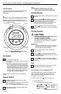
Three Thermostat Wires
If you have three wires for heating only and can operate
the fan using the FAN ON switch, this thermostat works
with your system. However, some hot water (zoned)
heating systems have three thermostat wires. The
thermostat will work only if you install an isolating relay on
these systems. For details, call Honeywell Customer
Assistance Center at 1-800-468-1502.
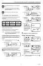
3 MOUNT WALLPLATE
IMPORTANT
Level for appearance only. The thermostat
functions normally even when not mounted level.
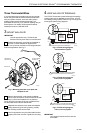
Position the decorator cover plate and wallplate on
the wall. Level the wallplate for appearance if
desired. Use a pencil to mark the two mounting holes that
best fit the application. See Fig. 3.
M12532
DECORATOR
COVER PLATE
WALL
WALLPLATE
PLASTIC SCREW
ANCHOR (2)
C
O
O
L
O
F
F
H
E
A
T
F
A
N
O
N
A
U
T
O
Fig. 3. Mounting decorator cover plate and
wallplate to wall.
Remove the decorator cover plate and wallplate
from the wall, and drill two 3/16-inch holes in the wall
(if drywall). For firmer wall material such as plaster or
wood, drill 7/32-inch holes. Gently tap provided anchors
into the drilled holes until flush with the wall.
Reposition the decorator cover plate and wallplate,
pulling wires through the wiring opening. Loosely
insert the mounting screws into the holes.
Level for appearance only; the thermostat functions
properly even when not level. Tighten the mounting
screws.
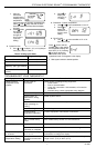
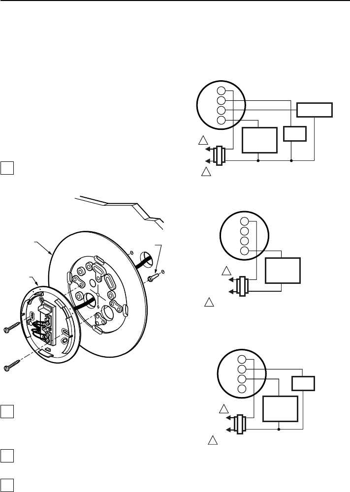
4 WIRE WALLPLATE TERMINALS
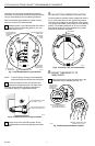
The CT2700 Thermostat is powered through the heating/
cooling system and is adaptable to most 4-wire, 18 to 30
Vac heating-cooling systems. Refer to Figs. 4 through 6 for
some typical system wiring diagrams.
L1
(HOT)
L2
1
1
W
Y
G
R
COOLING
CONTACTOR
FAN
RELAY
HEATING
PRIMARY
CONTROL
24V
POWER SUPPLY. PROVIDE DISCONNECT MEANS AND
OVERLOAD PROTECTION AS REQUIRED.
M12525
T8700
1
1
W
Y
G
R
HEATING
RELAY AND
FAN COIL
24V
POWER SUPPLY. PROVIDE DISCONNECT MEANS
AND OVERLOAD PROTECTION AS REQUIRED.
M12543
T8700
L1
(HOT)
L2
1
1
W
Y
G
R
FAN
COIL
COOLING
CONTACTOR
COIL
24V
POWER SUPPLY. PROVIDE DISCONNECT MEANS
AND OVERLOAD PROTECTION AS REQUIRED.
M12544
T8700
Fig. 4. CT2700 wiring diagram,
4-wire heat/cool system.
Fig. 5. CT2700 wiring diagram,
2-wire, heat-only system.
Fig. 6. CT2700 wiring diagram,
3-wire, cool-only system.
IMPORTANT
Use 18-gauge maximum wire to wire the
thermostat.