


69-0394—3 6
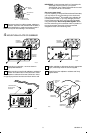
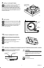
6 MOUNT THE THERMOSTAT
Note the tabs on the top inside edge of the thermostat
base. These fit the slots molded into the top of the
wallplate or subbase.
Hang the thermostat base on the wallplate or
subbase as shown in illustration.
Insert the two captive mounting screws located in
the bottom corners of the thermostat base (see
illustration); firmly tighten.
IMPORTANT:
Do not cycle heating system until step 7 is
completed.
TAB (2)
MOUNTING SLOT (2)
CAPTIVE
MOUNTING SCREWS
THERMOSTAT
BASE
WALLPLATE
OR SUBBASE
35
3
0
2
5
20
1
0
12
1
1
10
9
8
7
6
5
4
3
2
1
1
2
11
1
0
9
8
7
6
M3408
JUMPER WIRES
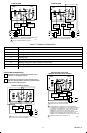
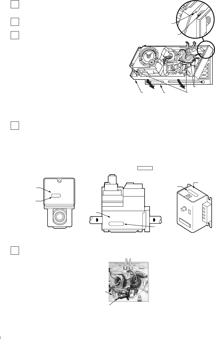
7 SET HEAT ANTICIPATOR LEVER
The thermostat adjustable heat anticipator must be
correctly set to accurately control the on-time length
of the system. An incorrect setting can result in room
temperature swings or burn out the anticipator and void the
thermostat warranty.
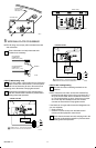
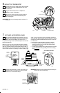
Make sure you have the current draw (anticipator setting)
for your system. This is the number you wrote in the box in
Step 3. If you were unable to find the current draw for Step 3,
this information can be found printed on the primary control
at the furnace or boiler. The primary control is usually a gas
valve, a relay or burner control box, Aquastat controller or
zone valve with the thermostat wires connected to it. These
controls are usually located behind the furnace cover. See
next illustration.
If current rating is still unavailable, proceed as follows:
• Connect the probes of an ac ammeter (0 to 2.0A for
example) between the R (or RH) and W terminals on
the wallplate or subbase.
• Let the system operate through the ammeter for at least
one minute before taking reading. Record the reading
here .
V8043E 1004 4
24V 50/60CY
.32 AMP
@ 60CY
8406
24 Vac 50/60 Hz
0.4 AMP
30 VAC
0.2 AMP
T
F
T
F
OIL BURNER CONTROL
SHOWS
CURRENT
DRAW
SHOWS
VOLTAGE
RATING
M6116B
FROM MAIN
FUEL SUPPLY
SHOWS
VOLTAGE
RATING
TO
BURNER
SHOWS
ANTICIPATOR
SETTING
TYPICAL GAS VALVE
ZONE VALVE
SHOWS
VOLTAGE
RATING
SHOWS
ANTICIPATOR
SETTING
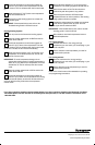
Move the heat anticipator to match the number you
recorded in Step 3 or found on the primary control
as shown above, or as recorded in Step 7.
IMPORTANT:
Most hot water systems require a setting of
1.3 times the valve current rating.
ANTICIPATOR
SETTING LEVER
ANTICIPATOR
SCALEPLATE
M9616