


69-0394—3 2
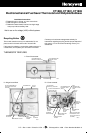
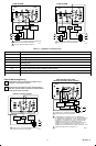
TABLE 1—THERMOSTAT AND SUBBASE APPLICATIONS.
a
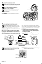
1 PREPARATION
Check thermostat and wallplate suitability for your heating or heating/cooling system. Refer to Table 1.
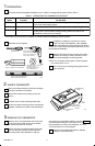
Assemble tools as required.
FLAT BLADE
SCREWDRIVER
HAND OR POWER
DRILL WITH 3/16 INCH
DRILL BIT, IF NEEDED TO
DRILL HOLES IN WALL
WIRE CUTTER/STRIPPER OR SHARP
KNIFE, IF NEEDED TO STRIP WIRES
MASKING TAPE, IF NEEDED
TO LABEL WIRES
DISCONNECTED FROM
OLD THERMOSTAT
LEVEL TO LEVEL THERMOSTAT
FOR ACCURATE OPERATION
M834A
If wallplate or subbase is mounted on a vertical
outlet box (check old installation), order 196393A
Cover Plate and Adapter Ring (see appropriate illustration
in Step 4). To order check your telephone directory for your
local Honeywell distributor.
Test to make certain that your heating and cooling
systems are working. If either one does not work,
contact your local heating/air conditioning dealer.
NOTE: Do not operate cooling sytem if outdoor tempera-
ture is below 50°F (10°C)
Tu rn off power to the heating/cooling system at the
main fuse panel.
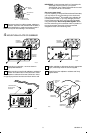
2 UNPACK THERMOSTAT
Remove and discard shipping wrap. Save package
of screws, instructions and receipt.
Remove thermostat cover by lifting up from the
bottom.
Carefully remove insert protecting switch bulbs.
Loosen two captive mounting screws, and separate
wallplate or subbase from back of thermostat base.
50
60
70
80
THERMOSTAT
COVER
LIFT
COVER
CAPTIVE
MOUNTING
SCREWS
THERMOSTAT
BASE
M9617
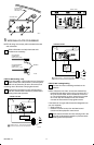
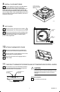
3 REMOVE OLD THERMOSTAT
Remove cover of old thermostat. If the cover does
not snap off when pulled firmly from the bottom,
check for a screw that locks on the cover.
Before removing the old thermostat from the wall,
look at it carefully to locate the heat anticipator
adjustment mechanism. (See illustration to help you
recognize the heat anticipator.) Make a note here
of that anticipator setting for future reference. If your
thermostat does not have a heat anticipator, do not be
concerned. Move on to next paragraph.
Loosen screws holding thermostat to wallplate,
subbase or wall and lift away.
Thermostat
Model
Subbase Wallplate
Included For Use With
CT1800 199986B Wallplate 2- or 3- wire, 150 to 30 volt control circuit. For gas or oil heating system or
3-wire zone valve heating system.
CT1801 Q682A1079 Subbase 4- or 5- wire, 15-30 volt control circuit. For gas or oil heating/cooling system.
CT1802 Q682B1227 Subbase 4- wire, 15 to 30 volt control circuit. For single-stage heat pump without
auxiliary heat or central electric heating/cooling systems that require the
thermostat to control the fan in heating.
a
Thermostat must be mounted on wallplate or subbase included in package to assure operation.