


69-0394—3 4
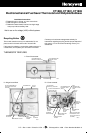
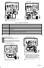
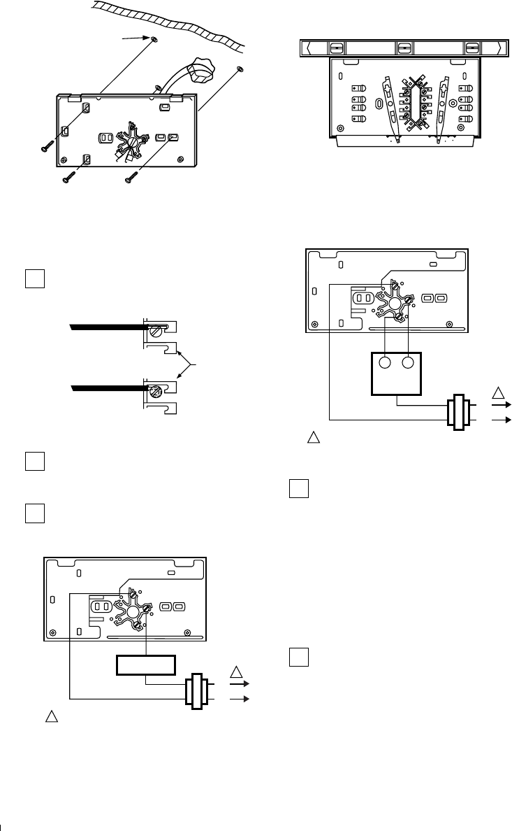
3 SCREW HOLES
WITH PLASTIC
ANCHORS
HEATING-ONLY
WALLPLATE
M9612
AUTO OFF
COOL
HEATON
FAN
B
O
W
Y
R
G
M2419
SPIRIT LEVEL
5 WIRE WALLPLATE OR SUBBASE
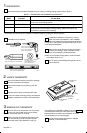
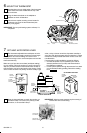
NOTE: All wiring must comply with local electrical codes
and ordinances.
Refer to illustration and strip thermostat wire
insulations as necessary.
BARRIER
FOR WRAPAROUND
CONNECTION—
STRIP 7/16 in. [11 mm]
FOR STRAIGHT
CONNECTION—
STRIP 5/16 in. [8 mm]
M1556B
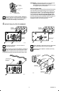
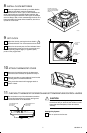
FOR CT1800 heating—only
For 2-wire system, connect either wire to R terminal
and the other wire to W terminal. For 3-wire system,
connect W wire to W terminal, R wire to R terminal, and
remaining wire to B terminal. Firmly tighten screws.
Push excess wire back into wall, and plug hole in
wall with nonflammable insulation to prevent drafts
from affecting thermostat operation.
L1
(HOT)
L2
POWER SUPPLY. PROVIDE DISCONNECT MEANS AND
OVERLOAD PROTECTION AS REQUIRED.
1
R
W
1
M2485B
3-WIRE SYSTEM
HEATING
VALVE OR
MOTOR
BW
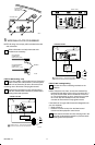
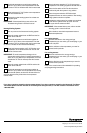
FOR CT1801 heating/cooling
Connect the wires to matching terminals on the
subbase.
NOTE: If there are four wires, connect wire marked R to
terminal RH and add a jumper wire to connect to RC. If
RC is left unconnected, the air conditioner will not turn
on. The 4-wire drawing on page shows how to jumper
RC to RH. Strip the insulation off the wire where it
connects to the terminals. Firmly tighten screws.
If the labels do not agree with the terminal designations on
your new subbase:
• Refer to Table 2
• Determine correct hookup from the listed control
function and the equipment control circuit.
Push excess wire back into wall, and plug hole in the
wall with nonflammable insulation to prevents drafts
from affecting thermostat operation.
HEATING RELAY
OR VALVE COIL
L1
(HOT)
L2
POWER SUPPLY. PROVIDE DISCONNECT MEANS AND
OVERLOAD PROTECTION AS REQUIRED.
1
R
W
1
M2484B
2-WIRE SYSTEM