


3 69-0394—3
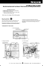
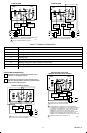
M6115
BULB
SWITCH
ANTICIPATOR
SCALE
ANTICIPATOR
SETTING LEVER
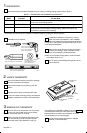
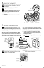
Disconnect wires from old thermostat, wallplate or
subbase. Tape each end and label with the letter of
the terminal designation to make reconnection easier. If
there are only two wires labeling is not necessary.
IMPORTANT:
If old thermostat has B or O terminals, this
thermostat cannot be used on your system.
EXCEPTION: The CT1802 Thermostat can be used
on a system with B or O terminals.
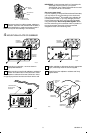
One or two extra wires?
If you are replacing a Honeywell Chronotherm
®
Thermostat,
you may find one or two wires that go to the clock termi-
nals on the Chrontherm
®
Thermostat wiring wallplate. Do
not allow them to touch, or you may damage your trans-
former. Disconnect the wires, and wrap them separately,
using electrical tape. Do not wrap them together. Place
the wires where they will not interfere with the operation of
the new thermostat. Record the colors and terminal
designation labels of the remaining wires.
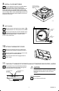
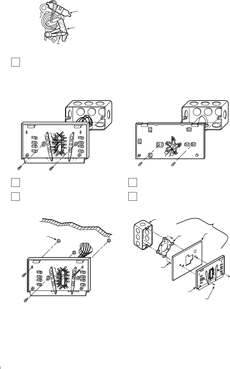
4 MOUNT WALLPLATE OR SUBBASE
M1553A
EXISTING
HORIZONTAL
OUTLET BOX
HEATING/
COOLING
SUBBASE
AUTO OFF
COOL
HEATON
FAN
R
G
O
W
Y
B
EXISTING
HORIZONTAL
OUTLET BOX
HEATING-ONLY
WALLPLATE
R
W
M856A
If mounting on outlet box , mount as shown in
appropriate illustration.
When mounting on wall, hold wallplate or subbase in
position and mark holes on wall. Use level to make
sure wallplate or subbase will be level. Drill 3/16 in. holes
and gently tap anchors into holes until flush with the wall.
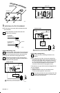
Position wallplate or subbase as shown in appropriate
figure, and loosely insert the screws supplied.
Carefully level the wallplate or subbase and firmly
tighten screws.
M1552A
AUTO OFF
COOL
HEATON
FAN
R
G
O
W
Y
B
3 SCREW HOLES
WITH PLASTIC
ANCHORS
HEATING/COOLING SUBBASE
M866
B
O
W
Y
R
G
VERTICAL
OUTLET
BOX
ADAPTER
RING
SUBBASE OR
WALLPLATE
COVER
PLATE
MOUNTING
SCREWS (2)
MOUNTING
SCREWS (2)
196393A
ASSEMBLY