


69-0642—1 6
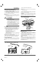
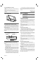
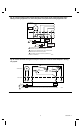
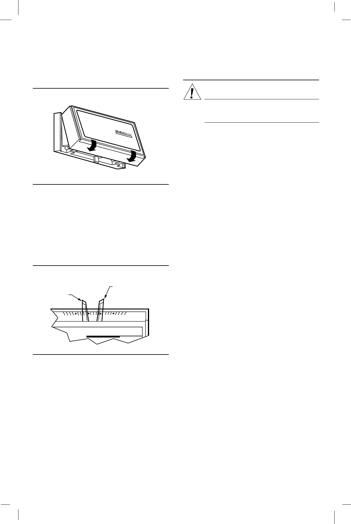
ATTACH THERMOSTAT COVER
Make sure the packing inserts in the thermostat base are
removed.
Place the two tabs on the upper edge of the cover into the
mounting slots in the thermostat base (Fig. 11).
Swing the cover downward until it catches at the bottom
of the base.
Fig. 11—Attach cover.
50
60
70
80
M8604
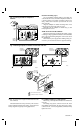
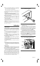
SET TEMPERATURE CONTROL LEVERS
The two levers on the top of the thermostat control the low
and high temperatures for energy savings and comfort con-
trol (Fig. 12). The lever on the left (blue mark) controls the
lower temperature. The lever on the right (red mark) controls
the higher temperature.
We recommend pushing the levers together at an appro-
priate temperature for either heat or cool until the occupant
programs the thermostat and makes the final temperature
selections.
Fig. 12—Temperature control levers.
50
60
70
80
HIGH TEMPERATURE
(RED MARK)
SET LEVER
LOW TEMPERATURE
(BLUE MARK)
SET LEVER
M859
SET SUBBASE SWITCHES (IF APPLICABLE)
The subbase system switch controls system operation as
follows:
HEAT: Heating system is controlled by the thermostat.
Cooling system is off.
COOL: Cooling system is controlled by the thermostat.
Heating system is off.
OFF: Both the heating and cooling systems are off. If the
fan switch is in the AUTO position, the fan is also off.
The subbase fan switch controls fan operation as follows:
ON: Fan operates continuously.
AUTO: Fan operates with the cooling equipment as
controlled by the thermostat or with the heating equip-
ment as controlled by the plenum switch. In electric
heat, heat pump, and fan coil systems, the fan is
controlled by the thermostat in heating and cooling.
To switch positions, use thumb or index finger to slide
lever to the desired position. Switch lever must stop in detent
over the desired function indicator mark for proper circuit
operation.
Checkout
CAUTION
Do not check operation by shorting across the
terminals of the system controls. This will damage
the heat anticipator.
HEATING-ONLY SYSTEM
Turn on power to the furnace.
Push both temperature setting levers together at least 5° F
[3° C] above the room temperature. The main burner should
come on. The fan will start when the furnace heats up.
Move both levers 5° F [3° C] below the room tempera-
ture. The burner should shut off.
Operate the entire heating system at least one complete
cycle.
If thermostat fails any test, refer to the Troubleshooting
Guide in the Owner’s Manual.
Reset both temperature setting levers to the desired
temperatures.
COOLING-ONLY SYSTEM
Turn on power to the cooling equipment.
Push both temperature setting levers together at least 5° F
[3° C] below the room temperature. The cooling equipment
will operate, and the fan will start. Allow for any time delay
that may be built into the compressor control circuit.
NOTE: To avoid compressor damage, do not operate the
system when outdoor temperature is below 50° F [10° C].
Refer to manufacturer recommendations.
Move both levers 5° F [3° C] above room temperature.
The cooling equipment and the fan should shut off.
Operate the entire cooling system at least one complete
cycle.
If thermostat fails any test, refer to the Troubleshooting
Guide in the Owner’s Manual.
Reset both temperature setting levers to the desired
temperatures.
HEATING/COOLING SYSTEM
Turn on power to the furnace and cooling system.
Place the system switch lever to HEAT and fan switch
lever to AUTO.
Push both temperature setting levers together at least 5° F
[3° C] above room temperature. The main burner should
come on. The fan will start when the furnace heats up. (If
central electric heat, fan coil or heat pump system, fan starts
immediately.)
Move both levers 5° F [3° C] below room temperature.
The burner should shut off.
Place the system switch lever to COOL and the fan switch
lever to AUTO. The cooling equipment will operate, and the
fan will start. Allow for any time delay that may be built into
the compressor control circuit.