


5 69-0642—1
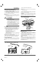
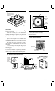
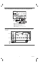
Fig. 7—Insert timer batteries.
BATTERY LOCATION FOR
(2) AAA BATTERIES;
INSTALL WITH POSITIVE
ENDS UP
M8585
SET TIMER
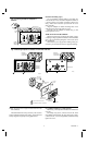
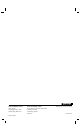
Adjust the timer by moving the knob clockwise .
Do not reverse the knob.
When time is correctly set, the time indicator arrow
(triangle shape) points to the correct time and the corre-
sponding daytime (light) or nighttime (dark) portion of the
program dial (Fig. 8).
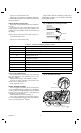
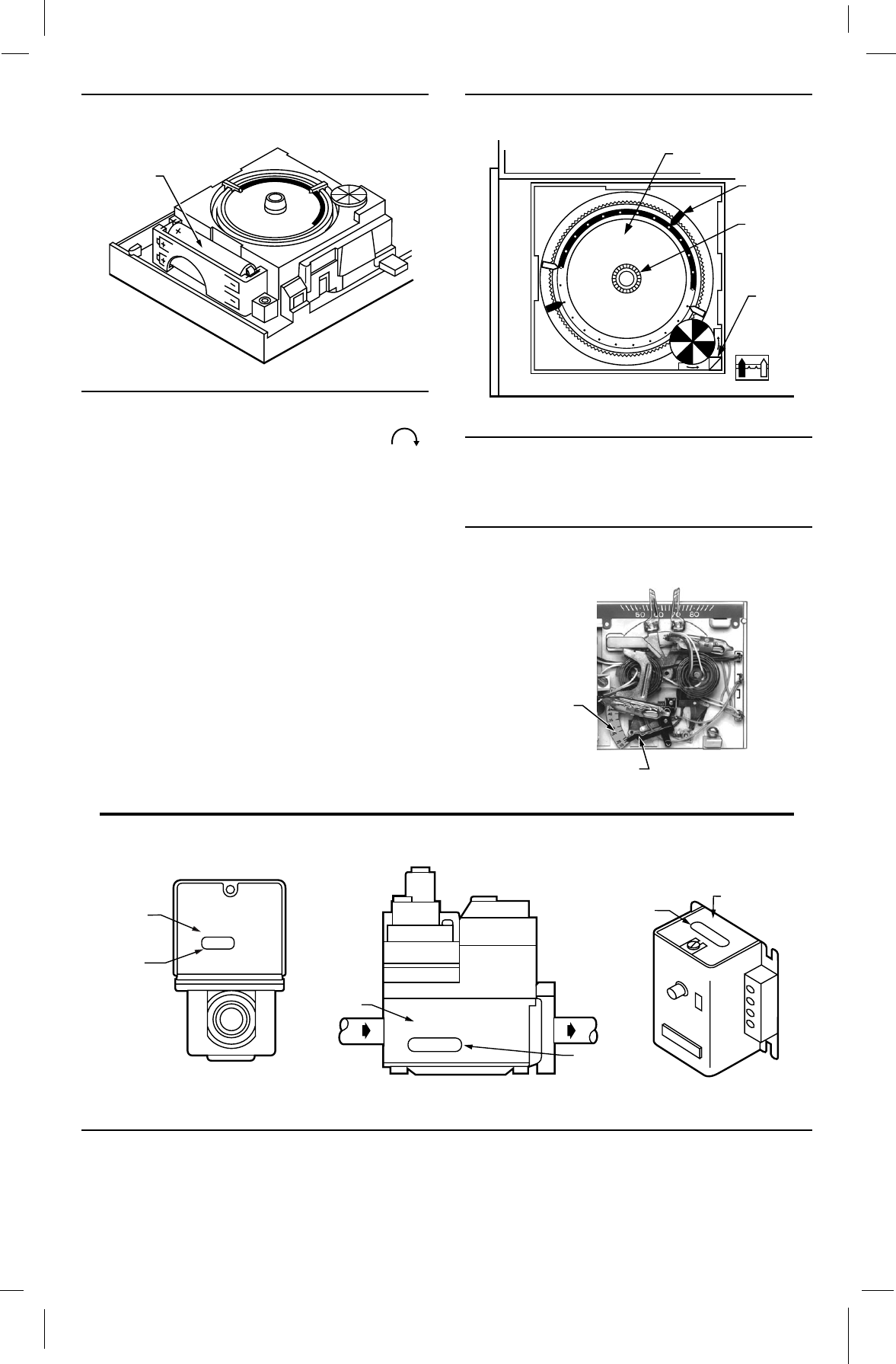
SET HEAT ANTICIPATOR
Adjust the heat anticipator lever to match the current
rating of the primary control for the proper cycle rate (Fig. 9).
Adjustable anticipation must be set for total current of heat
and fan control.
The current rating is usually stamped on the control or
valve (Fig. 10), or a setting may be given in the device
instructions.
If no current rating or heat anticipator setting is given,
measure the current with an ammeter. Proceed with the
following steps.
Remove the thermostat from the wallplate or subbase.
Connect an ac ammeter of appropriate range (about 0A to
2A) between the R and W terminals on the wallplate or
subbase, except for electric heat and heat pump systems.
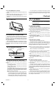
Fig. 8—Set timer.
TIMER
SETTING
KNOB
TIME
INDICATOR
ARROW
M821A
PROGRAM DIAL
PROGRAM
PIN (6)
Let the system operate for one minute.
Adjust the heat anticipator lever to match the number that
reads on the ammeter.
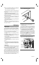
Fig. 9—Adjust heat anticipator.
M7317
ANTICIPATOR
SCALEPLATE
ANTICIPATOR
SETTING LEVER
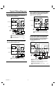
Fig. 10—Current rating of primary control.
V8043E 1004 4
24V 50/60CY
.32 AMP
@ 60CY
8406
24 Vac 50/60 Hz
0.4 AMP
30 VAC
0.2 AMP
T
F
T
F
OIL BURNER CONTROL
SHOWS
CURRENT
DRAW
SHOWS LOW
VOLTAGE
M6116A
FROM MAIN
FUEL SUPPLY
SHOWS
VOLTAGE
RATING
TO
BURNER
SHOWS
ANTICIPATOR
SETTING
TYPICAL GAS VALVE
ZONE VALVE
SHOWS
VOLTAGE
RATING
SHOWS
ANTICIPATOR
SETTING