


3 69-0642—1
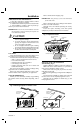
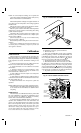
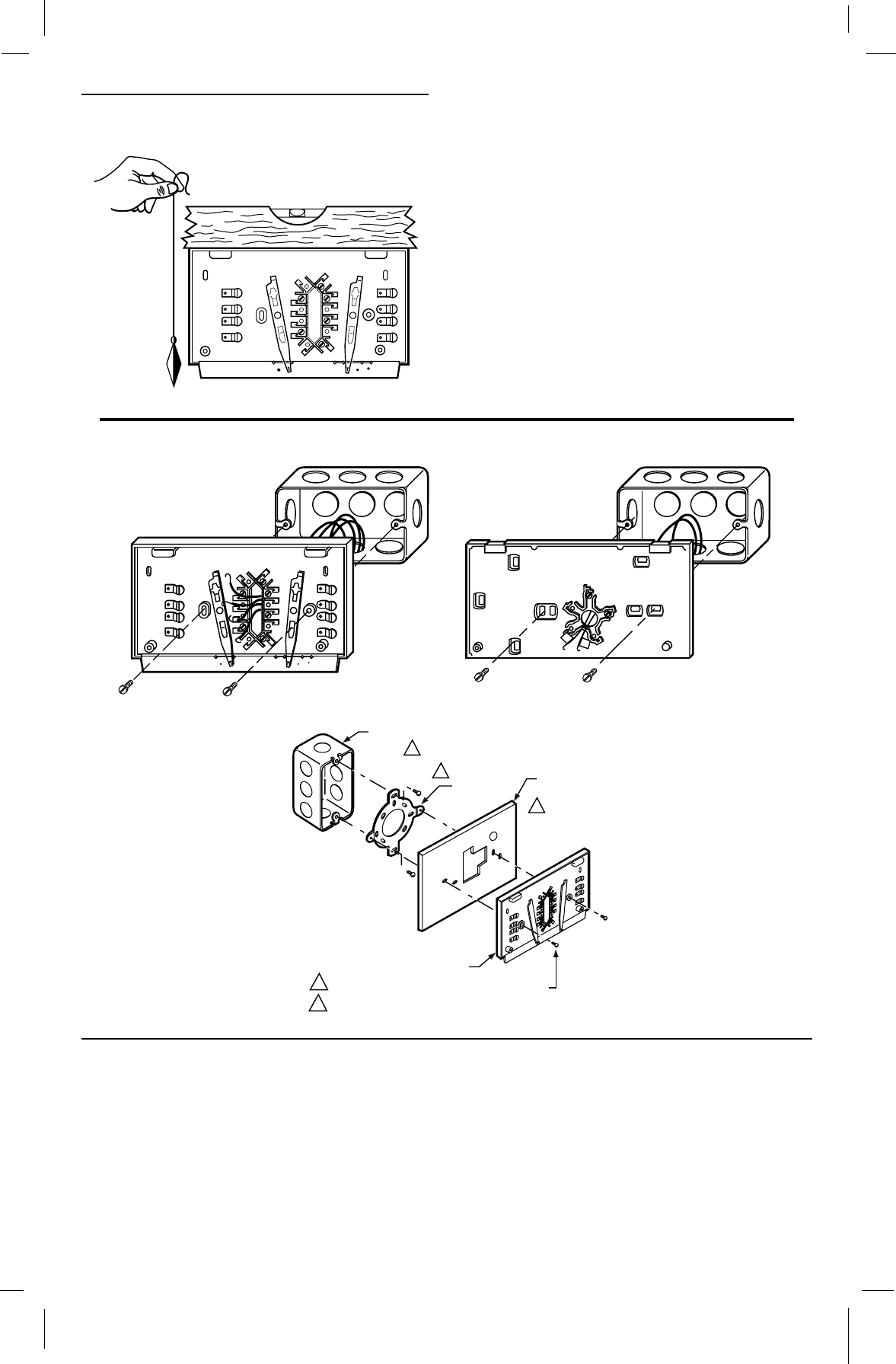
Fig. 3—Leveling methods for wallplate or
subbase.
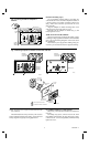
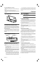
Outlet Box Mounting (Fig. 4)
Use a horizontally mounted outlet box if possible. If a
vertical outlet box is used, mount the wallplate or subbase on
a 193121A (beige) Cover Plate Assembly (ordered sepa-
rately). Follow the instructions provided with the cover
plate assembly.
Align the wallplate or subbase mounting holes on the
outlet box and loosely fasten with two screws.
Carefully level the wallplate or subbase (Fig. 3), and
firmly tighten the screws.
WIRE WALLPLATE OR SUBBASE
Follow the instructions provided by the heating, cooling,
or heating/cooling equipment manufacturer. If not available,
refer to the Typical Wiring Diagrams section at the end of
this publication.
Disconnect the power supply before making wiring con-
nections to prevent electrical shock or equipment damage.
AUTO OFF
COOL
HEATON
FAN
B
O
W
Y
R
G
M1555
SPIRIT LEVEL
PLUMB
LINE
PLUMB
BOB OR
WEIGHT
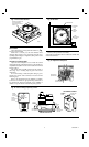
Fig. 4—Mounting wallplate or subbase on horizontal outlet box.
M1553A
EXISTING
HORIZONTAL
OUTLET BOX
HEATING/
COOLING
SUBBASE
AUTO OFF
COOL
HEATON
FAN
R
G
O
W
Y
B
EXISTING
HORIZONTAL
OUTLET BOX
WALLPLATE
R
W
M1816
M1554A
B
O
W
Y
R
G
VERTICAL
OUTLET
BOX
ADAPTER
RING
1
2
NOT INCLUDED WITH UNIT.
ACCESSORY PARTS AVAILABLE.
SUBBASE OR
WALLPLATE
1
2
2
COVER
PLATE
MOUNTING
SCREWS (2)
NOTE: All wiring must comply with local electrical codes
and ordinances.
This thermostat clock can be powered by a 24 Vac trans-
former with battery backup. Refer to Figs. 15 through 19 for
hookup diagrams of typical powering applications.
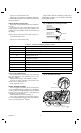
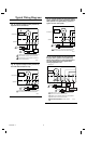
For Wallplate (Heating or Cooling Systems)
Refer to Fig. 5 and strip the thermostat wire insulation as
necessary.
For heating-only systems, connect wires to R, W, and C
(if applicable) terminals (Fig. 20). For cooling-only systems,
connect wires R, Y, and C (if applicable) terminals. Firmly
tighten the screws.