


69-0642—1 4
Push excess wire back into the wall.
Plug the hole in the wall with nonhardening caulk, putty,
or nonflammable insulation to prevent drafts from affecting
thermostat operation.
Subbase (Heating/Cooling Systems)
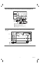
Refer to Fig. 5 and strip the thermostat wire insulation as
necessary.
Connect the wires to the corresponding terminals on the
subbase. If labels do not agree with your new subbase, refer
to Table 2 and the installation instructions furnished with
the subbase.
NOTE: If wiring a dual transformer system, only the O or
the B terminal may be used.
Push excess wire back into the wall.
Plug the hole in wall with nonhardening caulk, putty, or
nonflammable insulation to prevent drafts from affecting
the thermostat operation.
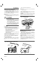
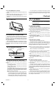
Fig. 5—Methods of connecting terminals.
BARRIER
FOR WRAPAROUND
CONNECTION—
STRIP 7/16 in. [11 mm]
FOR STRAIGHT
CONNECTION—
STRIP 5/16 in. [8 mm]
M1556B
TABLE 2—SUBBASE TERMINAL DESIGNATIONS.
Subbase Terminal Control Function
R Control transformer power.
R
c
Line side of 24V power supply; cooling side, 2 transformer heat/cool system.
R
h
Line side of 24V power supply; heating side, 2 transformer heat/cool system.
W Heating control circuit.
Y Cooling control circuit; jumper to W for heat pump compressor control if no
P terminal on subbase.
G Fan control circuit.
C Clock control (transformer common).
O Cooling damper or changeover/reversing valve, makes continuously in cool.
B Heating damper or changeover/reversing valve, makes continuously in heat.
P Heat pump contactor; P terminal on some models only.
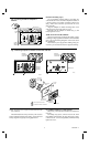
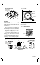
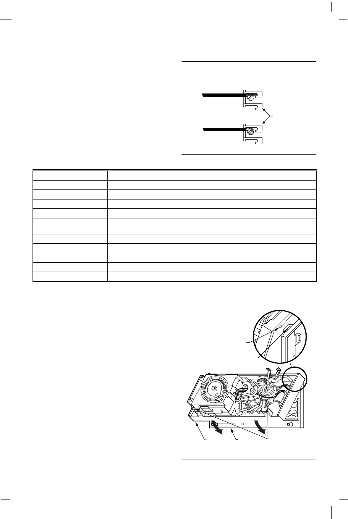
MOUNT THE THERMOSTAT
Note the tabs on the top inside edge of the thermostat
base. These tabs fit the slots molded into the top of the
wallplate or subbase.
Hang the thermostat base on the wallplate or subbase.
Insert the two captive mounting screws located in the
bottom corners of the base (Fig. 6).
Firmly tighten the screws.
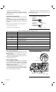
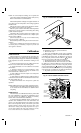
INSERT TIMER BATTERIES
Power is supplied to the clock by the 24 Vac transformer
or two AAA alkaline batteries (included), or by the heating
or cooling control circuit. Backup batteries may be installed
to supply power to the clock if power is interrupted when
using 24 Vac powering method.
Install the batteries in the thermostat (Fig. 7).
Once a year or when batteries are dead, replace with two
new AAA alkaline batteries. Properly dispose of old batter-
ies. We recommend Energizer
®
batteries.
Fig. 6—Thermostat mounting.
TAB (2)
MOUNTING SLOT (2)
CAPTIVE
MOUNTING SCREWS
THERMOSTAT
BASE
WALLPLATE
OR SUBBASE
35
30
25
20
10
12
11
10
9
8
7
6
5
4
3
2
1
12
11
10
9
8
7
6
M8674