


8
100507
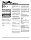
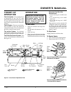
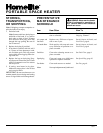
PORTABLE SPACE HEATER
SERVICE
PROCEDURES
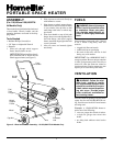
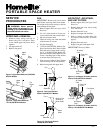
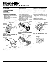
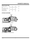
Air Output
Filter
Lint Filter
Air Intake
Filter
Filter End
Cover
Air Output
Filter
Lint Filter
Air Intake
Filter
Filter End
Cover
Fan
Guard
Figure 11 - Air Output, Air Intake, and Lint
Filters, 35/55,000 BTU/Hr Models
Figure 12 - Air Output, Air Intake, and Lint
Filters, 110/150,000 BTU/Hr Models
Fan
Guard
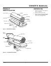
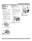
UPPER SHELL REMOVAL
1. Remove screws along each side of
heater using 5/16" nut-driver. These
screws attach upper and lower shells
together.
2. Lift upper shell off.
3. Remove fan guard.
Upper
Shell
Fan Guard
Upper
Shell
Fan
Guard
Figure 7 - Upper Shell Removal, 35/55,000
BTU/Hr Models
Figure 8 - Upper Shell Removal,
110/150,000 BTU/Hr Models
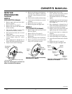
Figure 9 - Fan Cross Section
35/55/110,000 BTU/Hr Models
Figure 10 - Fan Cross Section
150,000 BTU/Hr Model
Fan
Fan
Setscrew
Motor Shaft
Motor
Flush
Motor
Shaft
Back of Flat
Surface on
Motor Shaft
Setscrew
Motor
WARNING: Never service
heater while it is plugged in, op-
erating, or hot. Severe burns and
electrical shock can occur.
AIR OUTPUT, AIR INTAKE,
AND LINT FILTERS
1. Remove upper shell (see Upper Shell
Removal).
2. Remove filter end cover screws using
5/16" nut-driver.
3. Remove filter end cover.
4. Replace air output and lint filters.
5. Wash or replace air intake filter (see
Preventative Maintenance Schedule,
page 6).
6. Replace filter end cover.
7. Replace fan guard and upper shell.
IMPORTANT:
Do not oil filters.
FAN
IMPORTANT:
Remove fan from motor
shaft before removing motor from heater.
The weight of the motor resting on the fan
could damage the fan pitch.
1. Remove upper shell (see Upper Shell
Removal).
2. Use 1/8" allen wrench to loosen set-
screw which holds fan to motor shaft.
3. Slip fan off motor shaft.
4. Clean fan using soft cloth moistened
with kerosene or solvent.
5. Dry fan thoroughly.
6. (35/55/110,000 BTU/Hr Models) Re-
place fan on motor shaft. Place fan hub
flush with end of motor shaft (see Fig-
ure 9). (150,000 BTU/Hr Model) Re-
place fan on motor shaft. Make sure set
screw is touching back of flat surface
on motor shaft (see Figure 10).
7. Place setscrew on flat of shaft. Tighten
setscrew firmly (40-50 inch-pounds).
8. Replace fan guard and upper shell.