


5
100507
OWNER’S MANUAL
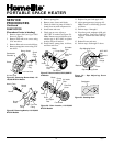
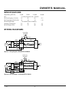
THEORY OF
OPERATION
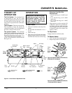
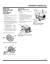
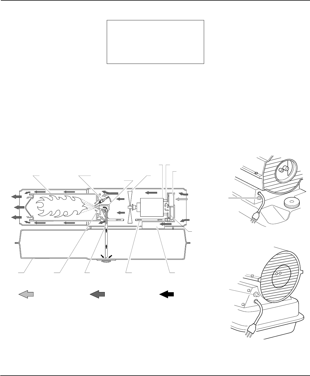
The Fuel System: The air pump forces
air through the air line. The air is then
pushed through the burner head nozzle. This
air causes fuel to lift from the tank. A fine
mist of fuel is sprayed into the combustion
chamber.
The Air System: The motor turns the fan.
The fan pushes air into and around the
combustion chamber. This air is heated and
provides a stream of clean, hot air.
The Ignition System: The electronic
ignitor sends voltage to the spark plug. The
spark plug ignites the fuel and air mixture.
The Flame-Out Control System: This
system causes the heater to shut down if the
flame goes out.
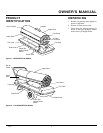
THEORY CUTAWAY
PFA/OV 003
Fuel
Filter
Air For Fuel
System
Air For Combustion
And Heating
Fuel
Combustion
Chamber
Air
Intake
Filter
Air Pump
Clean
Heated
Air Out
Cool
Air
In
Air
Output
Filter
Fuel
Tank
Figure 4 - Cross Section Operational View
Burner
Head
Spark
Plug
Motor
Fan
Electronic
Ignitor
Air Line
To Burner
Nozzle
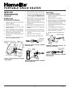
Extension Cord Wire Size
Requirements
• 6 to 10 feet long, use 18 AWG rated
cord
• 11 to 100 feet long, use 16 AWG
rated cord
• 101 to 200 feet long, use 14 AWG
rated cord
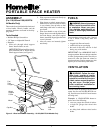
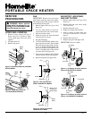
5. Plug extension cord into standard 120
volt/60 hertz, three-hole, grounded out-
let. Heater will start when extension
cord is plugged into outlet. If not, push
in flame-out control reset button (see
Figures 5 and 6).
To Stop Heater
Unplug extension cord from outlet.
To Restart Heater
1. Wait 2 minutes after stopping heater.
2. Repeat steps under To Start Heater.
IMPORTANT: Review and under-
stand the warnings in the
Safety
Information
section. They are
needed to safely operate this
heater. Follow all local codes
when using this heater.
To Start Heater
1. Follow all ventilation and safety infor-
mation.
2. Fill fuel tank with kerosene or No. 1
fuel oil.
3. Attach fuel cap.
4. Plug power cord of heater into three-
prong, grounded extension cord. Exten-
sion cord must be at least six feet long.
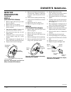
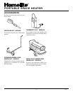
OPERATION
Flame-Out
Control
Reset
Button
Flame-
Out
Control
Reset
Button
Figure 6 - Flame-Out Control Reset Button,
110/150,000 BTU/Hr Models
Figure 5 - Flame-Out Control Reset Button,
35/55,000 BTU/Hr Models