


12
100507
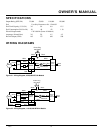
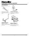
PORTABLE SPACE HEATER
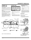
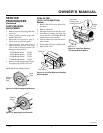
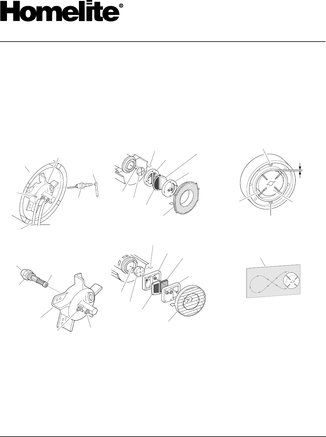
Burner Head
Spark
Plug
Cable
Spark
Plug
Combustion
Chamber
Screw
Fuel Line Hose
Air Line Hose
Figure 25 - Removing Burner Head, 110/
150,000 BTU/Hr Models
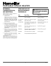
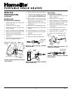
Burner
Head
Nozzle
Nozzle Face
Nozzle
Sleeve
Fuel Line
Fitting
Air Line
Fitting
Figure 26 - Removing Nozzle, 110/150,000
BTU/Hr Models
PUMP ROTOR
(Procedure if rotor is binding)
1. Remove upper shell (see Upper Shell
Removal, page 8).
2. Remove filter end cover screws using
5/16" nut-driver.
3. Remove filter end cover and air filters.
4. Remove pump plate screws using 5/16"
nut-driver.
SERVICE
PROCEDURES
Continued
5. Remove pump plate.
6. Remove rotor, insert, and blades.
7. Check for debris in pump. If debris is
found, blow out with compressed air.
8. Install insert and rotor.
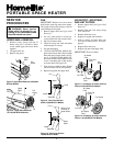
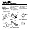
9. Check gap on rotor. Adjust to
.003"/.004" if needed (see Figure 29).
Note:
Rotate rotor one full turn to in-
sure the gap is .003"/.004" at tightest
position. Adjust if needed.
10. Install blades, pump plate, air filters,
and filter end cover.
11. Replace fan guard and upper shell.
12. Adjust pump pressure (see page 10).
Note:
If rotor is still binding, proceed
as follows.
13. Perform steps 1 through 6.
14. Place fine grade sandpaper (600 grit)
on flat surface. Sand rotor lightly in
“figure 8” motion four times (see Fig-
ure 30).
15. Reinstall insert and rotor.
16. Perform steps 10 through 12 above.
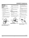
0
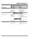
ROTOR
PFA/P 056
Pump Plate
Blade
Air Intake
Filter
Filter End
Cover
Fan Guard
Rotor
Insert
Air Output
Filter
Figure 27 - Rotor Location, 35/55,000 BTU/
Hr Models
0 ROTOR-Domestic PFA/P 059A
Blade
Pump
Plate
Air Intake
Filter
Filter End
Cover
Insert
Rotor
Air Output
Filter
Figure 28 - Rotor Location, 110/150,000
BTU/Hr Models
Fan Guard
Blade
Rotor
.003"/.004"
Gap
Measured
With
Feeler
Gauge
Gap Adjusting Screw
Sandpaper
Gap Adjusting Screw
Figure 30 - Sanding Rotor
Figure 29 - Gap Adjusting Screw
Locations