


8 Programming the Status System Chapter 2
Condition Register The condition register continuously monitors the hardware and firmware
status of the instrument. There is no latching or buffering for this register;
it is updated in real time. Condition registers are read-only.0
If there is no command to read a particular condition register, it is simply
invisible to you.
Transition Filter The transition filter specifies which types of bit state changes in the
condition register will set corresponding bits in the event register.
Transition filter bits may be set for positive transitions (PTR), negative
transitions (NTR), or both. Positive means a condition bit changes from
0 to 1. Negative means a condition bit changes from 1 to 0. Transition filters
are read-write. Transition filters are unaffected by *CLS (clear status) or
queries. They are set to instrument-dependent values at power
on and after *RST (reset).
If there are no commands to access a particular transition filter, it has a
fixed setting. This setting is specified in the instrument’s programming
guide or command dictionary. Most of our VXI instruments assign the
transition filter to detect positive transitions only.
Event Register The event register latches transition events from the condition register as
specified by the transition filter. Bits in the event register are latched, and,
once set, they remain set until cleared by a query or *CLS (clear status).
There is no buffering; so while an event bit is set, subsequent events
corresponding to that bit are ignored. Event registers are read-only.
Enable Register The enable register specifies which bits in the event register can generate a
summary bit. The instrument logically ANDs corresponding bits in the
event and enable registers, and ORs all the resulting bits to obtain a summary
bit. Summary bits are, in turn, recorded in another register, often the Status
Byte. Enable registers are read-write. Enable registers are not affected by
*CLS (clear status). Querying enable registers does not affect them. There
is always a command to read and write to the enable register of a particular
status group.
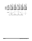
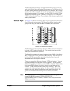
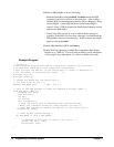
An Example
Sequence
Figure 2-2 illustrates the response of a single bit position in a typical status
group for various settings. The changing state of the condition in question
is shown at the bottom of the figure. A small binary table shows the state of
the chosen bit in each status register at the selected times T1-T5.