


19
MCBA FOR SPECIALISTS:
INSTALLER, SERVICE ENGINEER
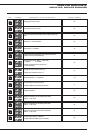
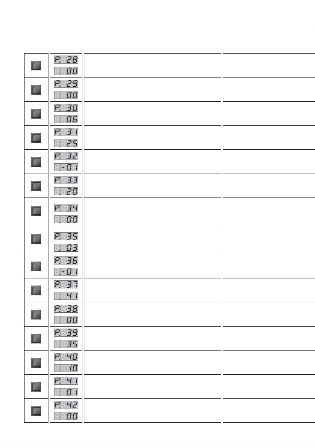
Heating lock time (sec x 10.2)
STEP
Hot water lock time (sec x 10.2)
STEP
Lock time to switch from hot water mode to heating mode (sec x
10.2)
STEP
Difference T1 - T2 for modulation
STEP
BUS address (-1 = disabled)
STEP
Increase the primary temperature value to generate hot water
(relative to the hot water temperature)
STEP
1st digit: heating circuit (AM3-11 – 4-way valve)
0 = disabled 5 = enabled
2nd digit: the demand for heat comes from:
0 = room thermostat
STEP
00
00
00
05
- 01
05
00
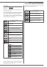
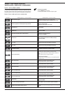
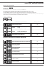
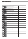
Key Display Description of the parameters Factory setting
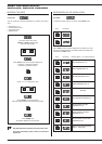
1st digit: Hot water circulator pump (= 1)
2nd digit: tank with NTC3 sensor (= 2)
STEP
Manual fan speed (- 01 = modulation)
12
- 01
11
00
60
30
01
00
STEP
1st digit: PWM pump operating speed
2nd digit: PWM pump speed during time-delay
STEP
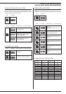
Holding temperature
STEP
Maximum temperature for the heating circuit outlet
(AM3-11 – 4-way valve)
STEP
Minimum temperature for the heating circuit outlet
(AM3-11 – 4-way valve)
STEP
Hysteresis of the heating circuit outlet temperature
(AM3-11 – 4-way valve)
STEP
1st digit: Special pump (0 = disabled)
2nd digit: Minimum disable cycle (0 = disabled)
STEP