


12
COMMISSIONING
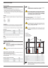
FILLING THE HOT WATER AND HEATING CIRCUITS
IMPORTANT
Hot water tank must be pressurised before the heating
circuit is filled.
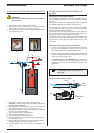
1. Close the primary circuit filling valves (A and B)
2. Open the stop valve (1) and the draw-off tap (8). Fill the tank
with the water from the tap; close the draw-off tap (8).
3. Fill the primary (heating) circuit by opening the valves (A and B)
and pressurising to 1 bar.
ACV BG 2000-M MODULATING PREMIX GAS
BURNER
Description and operating method:
The BG 2000-M modulating burner's output is constantly adjusted to
suit the fluctuating demand for heat, thus optimising operating
efficiency.
The gas tube is covered with a metal fibre (NIT), which, in addition to
its outstanding heat-exchange properties, increases its life.
The main parts are a venturi and a valve, a unit developed specially
by Honeywell for low NOx air/gas premix burners with automatic
ignition and flame detection by ionisation.
The pressure at the gas valve outlet is equal to the air pressure in
the neck of the venturi, less the offset.The fan sucks combustion air
through the venturi, into which the gas inlet emerges.
As it passes through, the air produces a pressure differential in the
constriction of the venturi and sucks the gas into the venturi outlet.
A perfect mix of air and gas then passes through the fan to the
burner tube.
This design ensures very quiet and safe operation:
• If there is an air blockage, the pressure differential in the venturi
falls, the gas flow diminshes, the flame goes out and the gas
valve closes: the burner is in safety shutdown mode.
• If there is a blockage in the chimney outlet, the air flow diminishes,
and the same reactions as those described above cause the
burner to shut down in safety mode.
• The BG 2000-M burner on the HeatMaster
®
201 is controlled by
an MCBA controller (Honeywell), which controls the safety of
operation of the burner and its modulation according to the
temperature.
The BG 2000-M burners are factory-set for
natural gas.
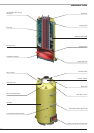
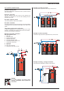
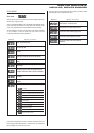
Air/gas mixture control system
12
3
4
5
2
6
7
8
9
10
11
Air
Venturi Fan
Air/gas
mixture
Gas flow adjuster
screw
Offset adjuster
screw
Gas
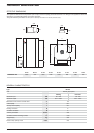
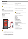
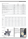
BURNER FEATURES
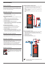
4. Open the automatic air vent located on top of the boiler.
IMPORTANT - the screw cap must be left loose to allow future
automatic venting to take place.
5. After venting the air from the system, bring the pressure up to the
static head plus 0.5 bar: 1.5 bar = 10 m and 2 bar = 15 m.
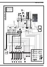
6. Check that the electrical connection and boiler room ventilation
conform to the relevant standards.
7. Switch the on/off switch to the ON position.
8. Set the temperature values
(see page 17)
.
9. Check the gas supply pressure
(see page 13)
.
10. When the burner is on, check that the flue gas discharge pipes
are completely gas tight.
11. After operating for five minutes, turn off the boiler and drain the
heating circuit again, maintaining a pressure of 1 bar.
12. Turn the appliance back on and check the combustion
(see
page 13)
.
AB