


4
DESCRIPTION
19
20
21
17
18
15
16
10
11
12
13
14
8
9
6
7
5
1
3
4
2
CONSTRUCTION FEATURES
Outer body
The outer body, containing the primary water, is made from STW 22
carbon steel.
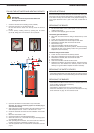
TANK-IN-TANK heat exchanger
The ring-shaped inner tank with its large heating surface for
producing domestic hot water is built of Chrome/Nickel 18/10
stainless steel. It is corrugated over its full height by an exclusive
production process and entirely argon arc welded by the TIG
(Tungsten Inert Gas) method.
Combustion gas circuit
The combustion gas circuit is paint-protected and comprises:
• Flue pipes
Depending on output, HeatMaster
®
200 models contain
several steel flue pipes with an internal diameter of 64 mm.
Each pipe is fitted with a baffle of special steel designed to
improve heat exchange and reduce flue gas temperature.
• Combustion chamber
The combustion chamber on HeatMaster
®
models is entirely
water cooled.
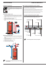
Insulation
The boiler body is fully insulated by rigid polyurethane foam with a
high thermal insulation coefficient, sprayed on without the use of
CFCs.
Casing
The boiler is covered by a steel jacket which has been scoured and
phosphated before being stove enamelled at 220°C.
Burner
The HM 200 F model is always delivered with a “RIELLO” RG4S 396
T1 fuel oil burner.
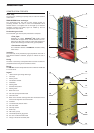
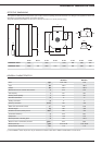
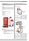
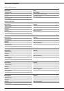
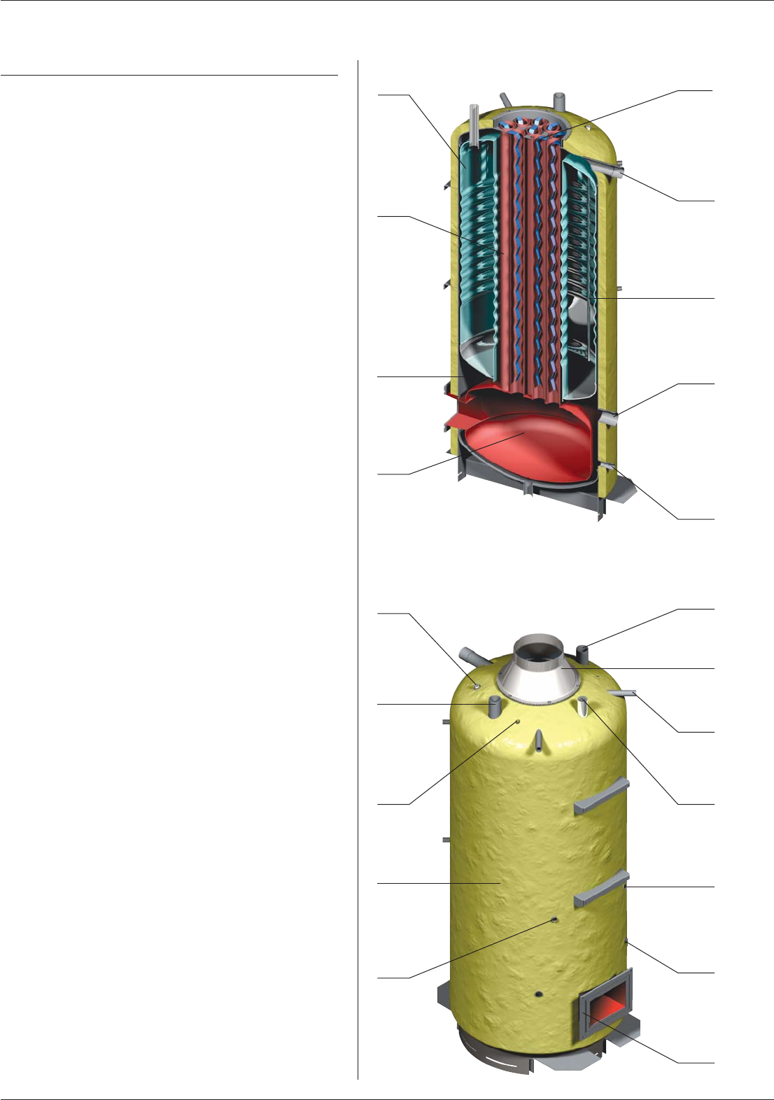
Legend
1. “Tank-in-Tank” type storage exchanger
2. Flue ways
3. Primary circuit
4. Combustion chamber
5. Turbulators
6. Heating outlet
7. Stainless steel pocket
8. Heating return
9. Boiler drain cock
10. Hot water priority thermostat bulb
11. Cold water inlet
12. Bulbs of the thermal reset high-limit 95°C thermostat and the
manual reset high-limit 103°C thermostat
13. Insulation
14. Low-water-level pressure switch
15. Hot water outlet
16. Chimney reducer
17. Steam trap
18. T&P valve
(optional)
19. Thermostat-pressure gauge bulb
20. 60 - 90°C control thermostat bulb
21. Flange of the burner chamber plate