


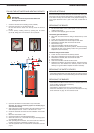

ELECTRICAL CONNECTIONS
Electrical supply
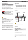
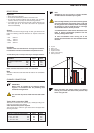
The boiler operates with a 230 V - 50 Hz single phase supply.
A double pole isolator with a 6 amp fuse or a 6 amp circuit breaker
switch to cut the power supply when servicing or repairing the boiler.
Conformity
Boiler installation must comply with the prevailing local standards and
legislation.
Safety
The stainless steel tank must be earthed separately.
The power to the boiler must be switched off before
any work is carried out.
10
INSTALLATION
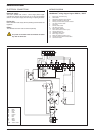
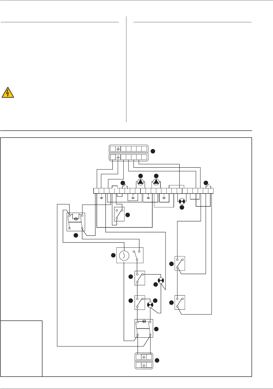
WIRING DIAGRAM
HeatMaster
®
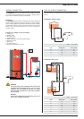
wiring diagram legend 200 N / 200 F
1. 230 V power connection plug
2. On/off switch
3. Temperature high limit cutoff indicator
4. Manual reset high limit thermostat
5. Primary circuit low water pressure indicator
6. Low water pressure switch
7. Time clock
8. Summer/winter switch
9. Hot water priority link
10. Burner lockout indicator
11. Room thermostat connection
(option)
12. Central heating pump
13. HeatMaster shunt pump
14. Burner plug connector
15. Water flow switch connection
(option)
16. Thermal reset high limit thermostat 95°C
17. Control thermostat
Electrical connection HeatMaster
®
200 N / 200 F
1 2 3 4 5 6 7 8 9 10 11 12 13 14 15 16 17 18 19 20 21 22 23
11
9
L1 N T1 T2 S3 B4
L1 N T1 T2 S3 B4
L1 N
L1 N
O
I
1
2
3
4
5
6
7
8
10
12 13
14
15
16
17
21
C
12
P
12
C
12
C
5
4
3
103 °C
95 °C
0 - 90 °C
21
C
Y/Gr
Br
Or
Or
W
W
R
Pk
B
B
W
B
Y
G
Gr
Y/Gr
Br
B
Y
G
Gr
Or
G
G
G
B
B
Or
B
B
Br
B
G
Br
Br
B
Or
Or Br Bk
B
B
B
BkBk
W
Pk
Bk
W
PkW
B. Blue
Bk. Black
Br. Brown
G. Grey
Gr. Green
Or. Orange
Pk. Pink
R. Red
V. Violet
W. White
Y. Ye l l o w
Y/Gr. Yellow / Green
B
Or
G
B
Or
B
B
R
B
R
B