


46
Heatilator • HEIR36, HEIR42, HEIR50 • 2285-900 Rev. D • 8/12
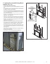
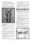
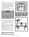
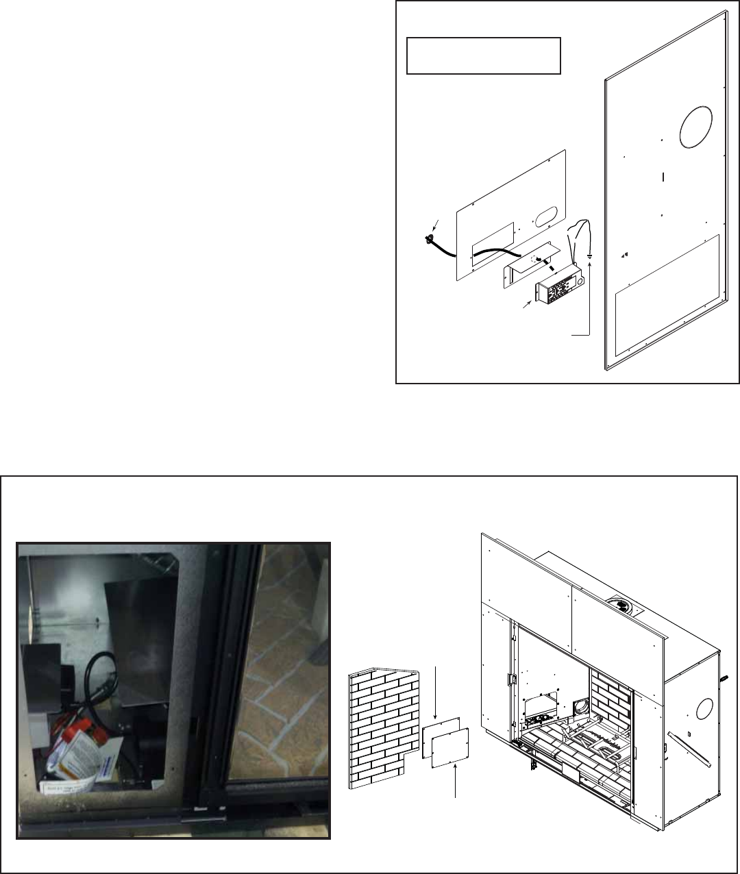
Figure 12.3 Junction Box Detail
NOTICE: DO NOT wire
110 VAC to wall switch.
GRN wire
inside box
Copper ground
attached to GRN
screw with GRN wire
WHT
WHT
BLK
BLK
14/2WG
Romex
Connector
D. Electrical Service and Repair
WARNING! Risk of Shock! Label all wires prior to dis-
connection when servicing controls. Wiring errors can
cause improper and dangerous operation. Verify proper
operation after servicing.
WARNING! Risk of Shock! Replace damaged wire with
type 105º C rated wire. Wire must have high temperature
insulation.
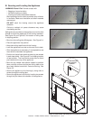
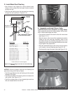
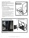
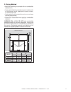
E. Junction Box Installation
If the box is being wired from the INSIDE of the appliance:
• The junction box is accessible through the front left
column if fi nishing materials have not been installed.
The junction box is also accessible through the fi rebox
access panel. See Figure 12.2.
• Remove the screw attaching the junction box/receptacle
to the outer shell, rotate the junction box inward to dis-
engage it from the outer shell. See Figure 12.3.
• Pull the electrical wires from outside the appliance through
the opening into the valve compartment and secure wires
with a Romex connector. See Figure 12.3
• Make all necessary wire connections to the junction box/
receptacle and reattach the junction box/receptacle to
the outer shell.
GASKET
COVER
Figure 12.2 Junction Box Access
ACCESS THROUGH LEFT COLUMN
(Prior to installation of non-combustible board)
ACCESS THROUGH FIREBOX
(After installation of non-combustible board)