


14
In the refrigeration cycle, the thermostatic expansion
valve bypass assembly check valve only allows refrigerant
ow through the thermostatic expansion valve and into
the evaporator coil. As the refrigerant vapor exits the coil
at the suction line, the check valve of the drain pan loop
check valve assembly prevents the refrigerant vapor ow
through the drain pan loop.
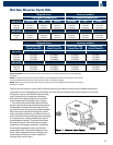
Factory engineered assemblies (kits) are available for both
shipped-loose and factory-installed at an additional cost
to complete the reverse cycle piping and components.
The suction line check valve assembly includes the
suction line check valve and the piping for both the
suction line and the connection to the drain pan loop
inlet header. In order for the suction line check valve
assembly to be mounted, the drain pan loop check
valve assembly must be used. The drain pan loop check
valve assembly includes the check valve, suction line
tee and a bent pipe. The thermostatic expansion valve
bypass assembly option includes the check valve, tee
and necessary piping. In order for the thermostatic
expansion valve bypass assembly option to be complete,
a thermostatic expansion valve must be selected by the
sales engineer. The thermostatic expansion valve bypass
assembly option is dependent on the body style of the
thermostatic expansion valves which includes the Sporlan
SQE, SBF, EG and the Alco HFESC body styles. The factory-
installed thermostatic expansion valve bypass assembly
option must have the thermostatic expansion valve selection included on the order for the hot gas unit cooler.
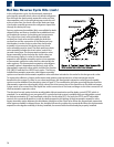
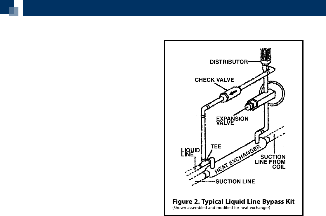
To increase the eciency, higher performance and greater system protection, a heat exchanger may be
benecial to the system. In order to use a heat exchanger, the thermostatic expansion valve bypass assembly
option must be modied. See the piping view in Figure 2. The modication includes rerouting the pipe from the
thermostatic expansion valve bypass check valve to the inlet connection of the liquid line to the heat exchanger.
A pipe needs to be routed from the liquid line outlet connection of the heat exchanger to the inlet connection of
the thermostatic expansion valve.
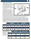
The electrical control option includes an adjustable defrost termination and fan delay control (DTFD) which is
standard. For an additional cost, an optional (2) control electrical system is available with one adjustable control
for defrost termination (DT) and one xed control for the fan delay (FD). For both the DTFD and DT adjustable
controls, the remote bulb position is with the bulb strapped to the piping of the thermostatic expansion valve
bypass assembly option between the distributor sideport and the check valve. When the thermostatic expansion
valve bypass assembly is shipped-loose, the installer will need to position the remote bulb. When the thermostatic
expansion valve bypass assembly is factory-installed, the remote bulb should already be properly installed.
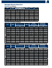
Hot Gas Reverse Cycle Kits (cont.)