


53Heat & Glo • XLR-PLUS-N-AU, XLR-PLUS-PB-AU • 2264-900 Rev. M • 7/12
13
Finishing
A. FramingandFinishingInstructions
WARNING! Risk of Fire! Comply with all minimum clear-
ances to combustibles as specied. Framing closer than the
minimums listed must be constructed entirely of noncom-
bustible materials (i.e., steel studs, concrete board, etc.)
FinishingInstructions
It is important to follow the framing and nishing instruc-
tions to ensure proper placement of replace into the sur-
rounding framing/nishing materials.
Wall sheathing materials 3/8 in. (10 mm) thick are
specied in this installation manual to properly align with
the factory-installed non combustible material.
WARNING! Risk of Fire! DO NOT remove the factory-
installed non-combustible board or cover it with combus-
tible material, such as:
• Drywall (gypsum board)
• Plywood
• Materials that do not meet the ASTM E 136 Non-com-
bustibility standard (below).
Removal of factory-installed, non-combustible board and/
or use of materials not meeting the ASTM E 136 standard
may cause re.
NOTE: Unit must be installed (and gas connected)
prior to plaster sheeting.
Non-CombustibleMaterialsSpecication
Material which will not ignite and burn. Such materials are
those consisting entirely of steel, iron, brick, tile, concrete,
slate, glass or plasters, or any combination thereof.
Materials that are reported as passing ASTM E 136,
StandardTestMethodforBehaviorofMaterialsina
VerticalTubeFurnaceat750ºC(1385ºF)andUL763
shall be considered non-combustible materials.
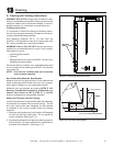
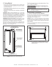
SettingtheFireplaceintotheFraming
Unlike many traditional, single-sided Heat & Glo replaces,
this replace is recessed into surround framing. The left
and right nailing tabs were designed so the replace
is recessed to the correct location within the framing
materials.
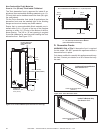
1. Bend two nailing tabs away from replace 180 degrees
on both left and right nailing tabs. Do not adjust the
column standoffs. See Figure 13.1.
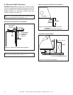
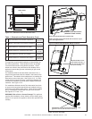
2. Screw each nailing tab to the adjoining framing material.
Ensure that the air space clearance is maintained on
the sides of the replace. See Figure 13.2.
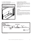
Figure13.1NailingTabsInstallationPosition
Figure13.2FrontSideFinishingDetail
FRAMING
1-1/8 in. (30 mm)
3/8 in (10 mm) BUILDING MATERIAL
1-1/2 in. (37 mm)
NAILING
TABS