


Heat & Glo • XLR-N-CE, XLR-PB-CE • 2198-900 Rev. J • 5/1254
16
ComponentAccess
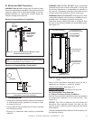
WARNING! Risk of Fire, Electric Shock and Burns!
Turn off power to module and valve by unplugging the 6V
transformer from the junction cord and remove batteries
from battery tray (if installed), before removing xed glass
assembly.
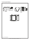
A. DecorativeFrontandFixedGlassAssem-
blyRemoval
• The decorative front can be removed by unscrewing (4)
screws that secure the decorative front to the replace.
Refer to the installation instructions that were included
with the decorative front option for more detailed
instruction.
• Refer to Section 14.E for fixed glass removal and
installation instructions.
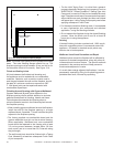
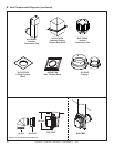
Figure16.2ValveComponents
GASVALVE
CONTROL
MODULE
ON/OFF/REMOTE
SWITCH
DCADAPTER
BATTERY
PACK
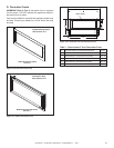
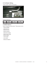
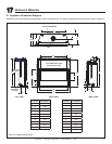
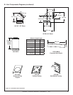
D. MediaTrayRemoval
1. Remove decorative front and xed glass assembly.
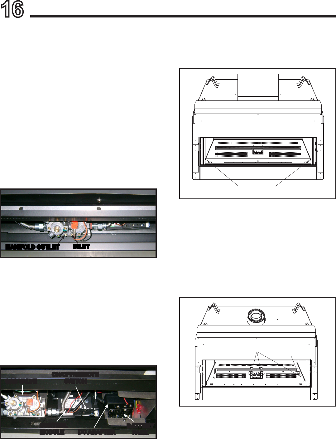
2. Remove media tray by removing three screw located
on the front edge of the media tray. See Figure 16.3.
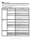
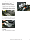
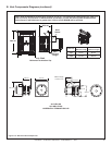
Figure16.4RemoveBurnerAssembly
REMOVE SCREWS
BURNER CLIP
BASE PAN
E. BurnerandBasePanRemoval
Once the media tray is removed, the burner assembly
and base pan may be removed.
1. Remove burner assembly by removing two screws that
secure the burner to the pilot assembly bracket and
remove the one screw that secures the burner clip that
secures the burner to the base pan. See Figure 16.4.
2. Once the burner is removed, the base pan can be
removed by lifting “up” and “out”.
Figure16.3RemoveMediaTray
REMOVE SCREWS
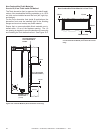
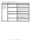
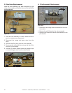
B. ValvePressureTaps
The pressure taps are available through the front of the
appliance. The decorative mesh front and replace gas
assembly must be removed to gain access to the pres-
sure taps.
INLET
MANIFOLDOUTLET
Figure16.1PressureTaps
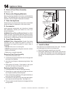
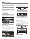
C. ControlModuleAccess
The control module on this appliance can be accessed by
following the following steps:
1. Remove decorative front and xed glass assembly.
2. Locate the control module. See Figure 16.2.
3. Unplug the black wire from the transformer, unplug the
wire harness to the valve, and unplug the orange and
white wires from the pilot assembly.
4. Verify the replacement module is installed to the wire
diagram listed in Section 12.