


24
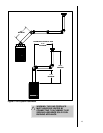
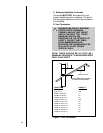
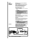
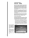
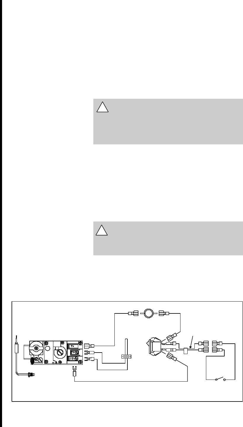
Figure 11. Standing Pilot Ignition Wiring Diagram
!
!
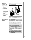
Step 9
Wiring the
Fireplace
NOTE: Electrical wiring must be installed by a
licensed electrician.
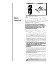
Caution: Disconnect remote controls if you are
absent for extended time periods. This will
prevent accidental fireplace operation.
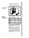
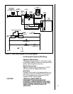
For Standing Pilot Ignition Wiring
Appliance Requirements
• This appliance DOES NOT require 110-120 VAC to
operate.
WARNING
DO NOT CONNECT 110-120 VAC TO THE
GAS CONTROL VALVE WALL SWITCH
OR THE APPLIANCE WILL
MALFUNCTION AND THE VALVE WILL
BE DESTROYED.
Optional Accessories
Optional remote control kits require that 110-120 VAC
be wired to the factory installed junction box before the
fireplace is permanently installed.
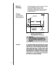
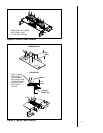
Wall Switch
Position the wall switch in the desired position on a
wall. Run a maximum of 25 feet (7.8 m) or less length
of 18 A.W.G. minimum wire and connect it to the
fireplace ON/OFF switch pigtails.
WARNING
DO NOT CONNECT 110-120 VAC TO THE
WALL SWITCH OR THE CONTROL
VALVE WILL BE DESTROYED.
CAUTION
LABEL ALL WIRES PRIOR TO DISCONNECTION
WHEN SERVICING CONTROLS. WIRING
ERRORS CAN CAUSE IMPROPER AND
DANGEROUS OPERATION. VERIFY PROPER
OPERATION AFTER SERVICING.
HI-TEMP LIMIT SWITCH
ON
OFF
ON/OFF SWITCH
GAS VALVE
THERMOPILE
BLACK S1
OPTIONAL WALL SWITCH,
THERMOSTAT OR REMOTE
REMOTE SWITCH
PIGTAIL
BLACK L1
BLACK L2
WHITE T2
RED T1
THERMOCOUPLE