


22
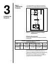
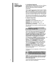
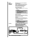
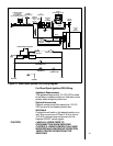
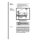
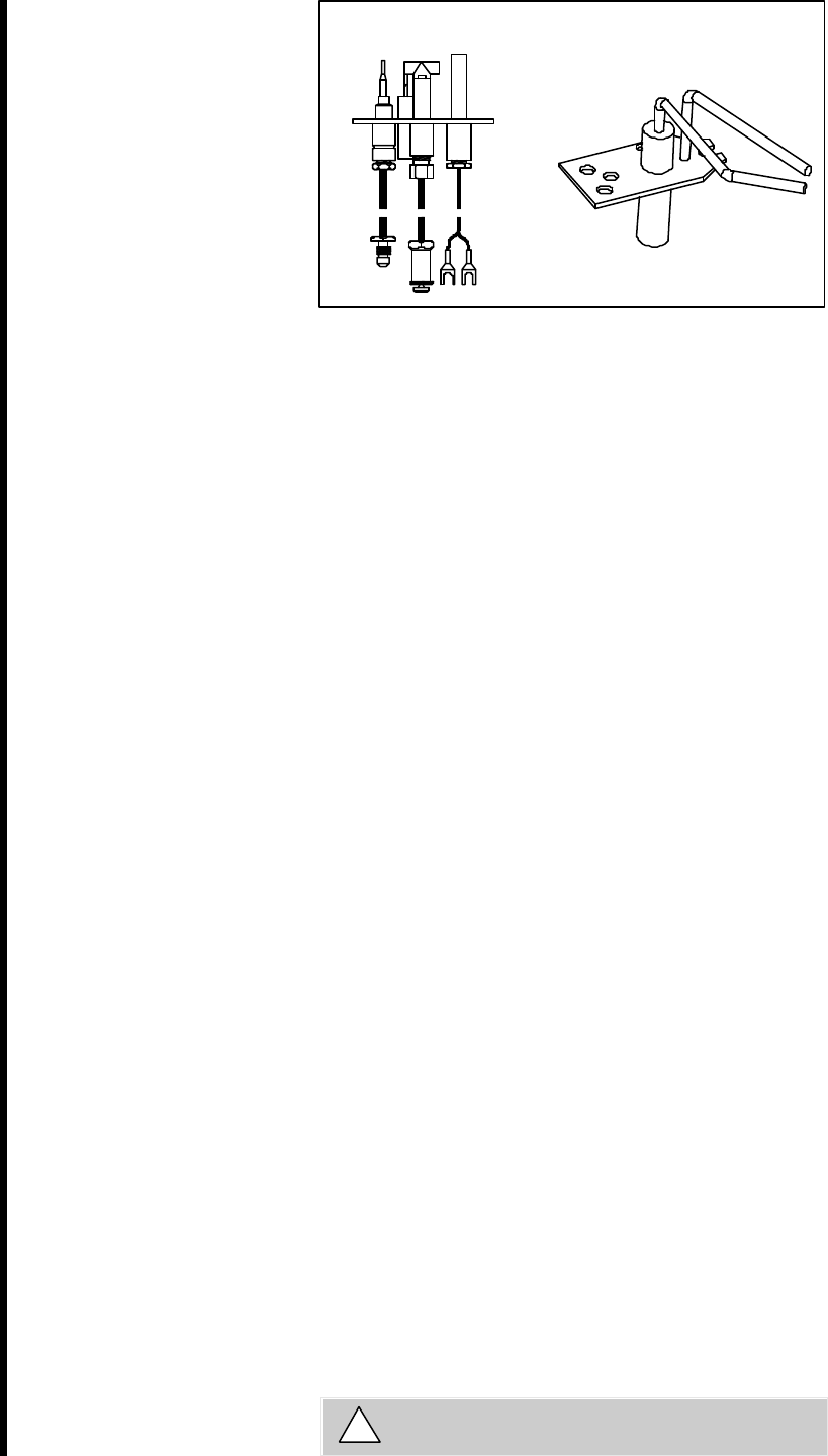
STANDING PILOT
DSI IGNITION
Figure 9. Gas Controls Systems
Step 7
The Gas
Supply Line
NOTE: Have the gas supply line installed in
accordance with local building codes by a qualified
installer approved and/or licensed as required
by the locality. (In the Commonwealth of
Massachusetts installation must be performed by
a licensed plumber or gas fitter).
NOTE: Before the first firing of the fireplace, the
gas supply line should be purged of any trapped air.
NOTE: Consult local building codes to properly
size the gas supply line leading to the 1/2 inch
(13 mm) hook-up at the unit.
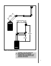
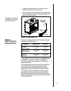
This gas fireplace is designed to accept a 1/2 inch
(13 mm) gas supply line. To install the gas supply line:
• A listed (and Commonwealth of Massachusetts ap-
proved) 1/2 inch (13mm) tee-handle manual shut-
off valve and a listed flexible gas connector are
connected to the 1/2 inch (13mm) inlet of the con-
trol valve. NOTE: If substituting for these compo-
nents, please consult local codes for compliance.
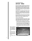
• The gas line may be run from either side of the
fireplace provided the hole in the outer wrap does
not exceed 2 inches in diameter and it does not
penetrate the airtight firebox.
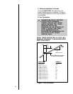
• The gap between the supply piping and gas ac-
cess hole can be plugged with non-combustible
insulation to prevent cold air infiltration.
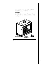
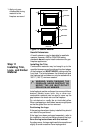
• Locate the gas line access hole in the outer casing of
the fireplace.
• Remove decorative door by lifting up away to gain
access to the gas control and shut-off valve, insert
the gas supply line through the gas line hole, and con-
nect it to the shut-off valve.
• When attaching the pipe, support the control so that
the lines are not bent or torn.
• After the gas line installation is complete, all connec-
tions must be tightened and checked for leaks with a
commercially available, non-corrosive leak check so-
lution. Be sure to rinse off all leak check solution fol-
lowing testing.
WARNING: DO NOT USE AN OPEN FLAME TO
CHECK FOR GAS LEAKS.
!
u
u
u