


Heat & Glo • SLR32 • 2269-900 Rev. E • 4/1246
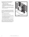
C. Gas Connection
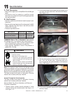
• Refer to Reference Section 16 for location of gas line
access in appliance.
• Gas line may be run through knockout(s) provided.
• The gap between supply piping and gas access hole may
be caulked with caulk with a minimum of 300ºF continuous
exposure rating or stuffed with non-combustible, unfaced
insulation to prevent cold air infi ltration.
• Ensure that gas line does not come in contact with outer
wrap of the appliance. Follow local codes.
• Pipe incoming gas line into valve compartment.
• Connect incoming gas line to the 1/2 in. (13 mm)
connection on manual shutoff valve.
WARNING! Risk of Fire or Explosion! Support control
when attaching pipe to prevent bending gas line.
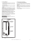
• A small amount of air will be in the gas supply lines.
WARNING! Risk of Fire or Explosion! Gas build-up dur-
ing line purge could ignite.
• Purge should be performed by qualified service
technician.
• Ensure adequate ventilation.
• Ensure there are no ignition sources such as sparks
or open fl ames.
Light the appliance. It will take a short time for air to purge
from lines. When purging is complete the appliance will
light and operate normally.
WARNING! Risk of Fire, Explosion or Asphyxiation!
Check all fi ttings and connections with a non-corrosive
commercially available leak-check solution. DO NOT use
open fl ame. Fittings and connections could have loos-
ened during shipping and handling.
WARNING! Risk of Fire! DO NOT change valve settings.
This valve has been preset at the factory.
D. High Altitude Installations
NOTICE: If the heating value of the gas has been reduced,
these rules do not apply. Check with your local gas utility
or authorities having jurisdiction.
When installing above 2000 feet elevation:
• In the USA: Reduce burner orifi ce 4% for each 1000 feet
above 2000 feet.
• In CANADA: Reduce burner orifi ce 10% for elevations
between 2000 feet and 4500 feet. Above 4500 feet,
consult local gas utility.
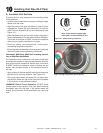
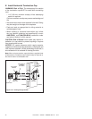
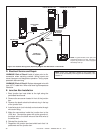
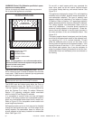
Valve Pressure Taps
The pressure taps are accessible through the front of the
appliance. The decorative mesh front and fi replace gas
assembly must be removed to gain access to the pressure
taps. See Figure 11.5.
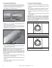
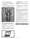
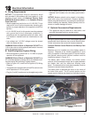
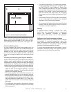
Figure 11.4. Disconnect Gas Valve
Note: The manifold and inlet pressure tabs can be ac-
cessed from the front of the fi replace when valve assembly
is installed.
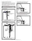
Note: Install the gas supply line in accordance with local
codes, if any. If not, follow ANSI 223.1. Installation should
be done by a qualifi ed installer approved and/or licensed
as required by the locality. (In the Commonwealth of
Massachusetts installation must be performed by a
licensed plumber or gas fi tter).
Note: A listed (and Commonwealth of Massachusetts ap-
proved) 1/2 in. (13 mm) T-handle manual shut-off valve
and fl exible gas connector are connected to the 1/2 in. (13
mm) control valve inlet.
• If substituting for these components, please consult
local codes for compliance.
Figure 11.5 Valve Pressure Taps and Remote Receiver Location
PRESSURE TAPS
VALVE BRACKET SCREW