


40
E. Combustible Mantel
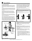
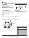
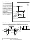
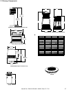
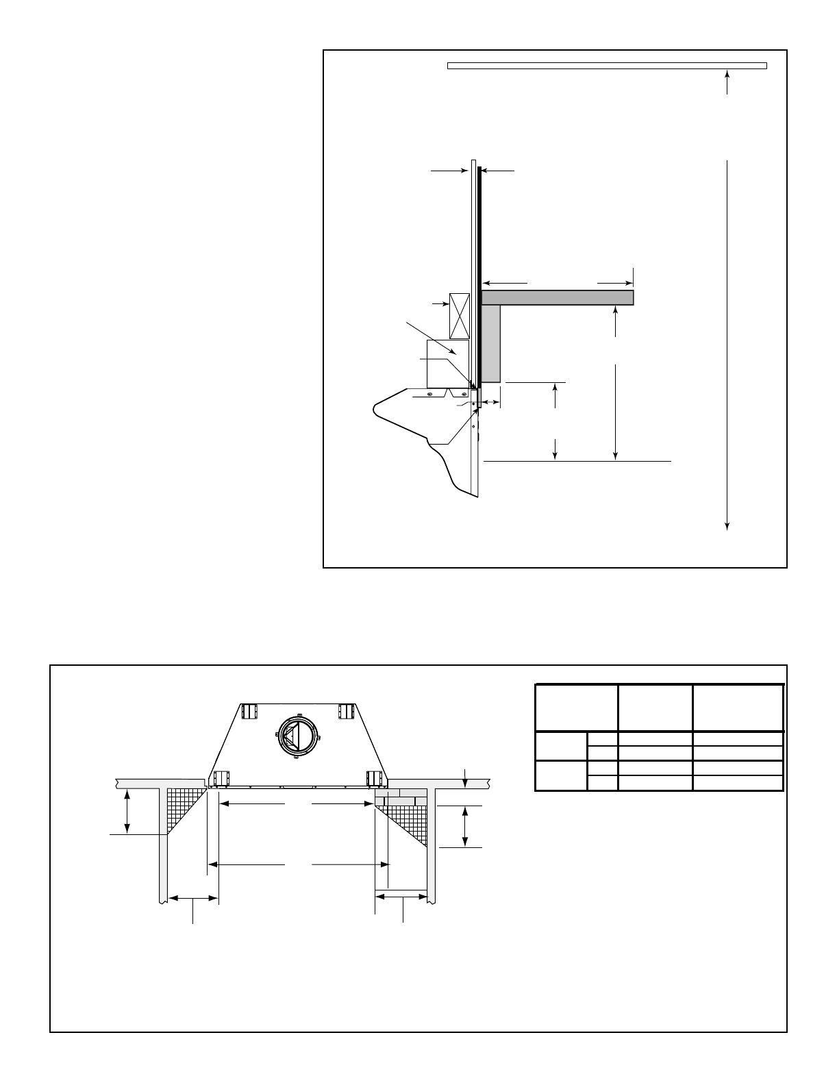
• Refer to the shaded areas of Figure
11.11 for locations and dimensions of a
combustible mantel.
• A combustible mantel may be positioned
no lower than 12 in. (305 mm) above the
top of the replace opening.
• A combustible mantel may have a
maximum depth of 12 in. (305 mm).
• Combustible trim and materials cannot
be placed within 6 in. (152mm) of the
replace opening (top or sides).
• Combustible materials projecting more
than 1 1/2 in. (38 mm) shall not be placed
within 12 in. (305 mm) from the top of
the replace opening.
• Combustible trim must not cover the
metal surfaces of the replace.
• Mantel clearance is in accordance with
Section 7-3.3.3 of ANSI/NFPA211.
6 ft (1829 mm)
minimum
base of fireplace
to ceiling
Combustible Wall
2 x 4 stud wall
Mantel
Standoffs
Measured from top of fireplace opening
12 in./305 mm
1 1/2 in./38 mm
maximum
12 in./305 mm
minimum
6 in./152 mm
minimum
Combustible
Decorative Facing
Seal joint with
non-combustible
sealant
Non-combustible
Decorative Facing
such as:
Steel, iron, brick,
tile, concrete, slate,
glass, plasters.
Figure 11.11 Clearances to Mantels or other Combustibles above Fireplace
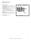
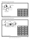
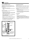
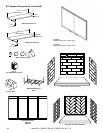
F. Sidewalls/Surrounds
• Adjacent combustible sidewalls must be located a minimum of 12 in. (305 mm) from the replace opening.
• Combustible or non-combustible mantel legs, surrounds and stub walls may be constructed per Figure 11.12.
B
A
12 in.
[305 mm]
9 3/4 in.
[248 mm]
12 in.
[305 mm]
10 3/4 in.
[273 mm]
FLUSH
FRONT
4 in.
[102 mm]
BRICK
FRONT
50° angle
39° angle
Grid represents 1 in. scale
A
Fireplace
Opening
B
Outside
Dimensions
in.
36 42
mm
914 1067
in.
42 48
mm
1067 1219
EM-415
EM-485
Model #
Figure 11.12 Mantel Leg or Wall Projections (acceptable on both sides of opening)
Heat & Glo • EM-415, EM-485 • 33056 • Rev AF• 7/12