


23
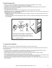
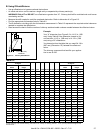
• Hearth & Home Technologies Inc recommends using
UL181 Class 0 or Class I rigid or flexible ducting.
• Secure flex duct with metal tape, screws or wire ties.
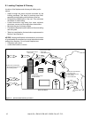
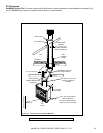
Outside Air
Hood
2 Wire Ties
Flexible Duct
(not supplied)
Inlet Ring
Figure 7.5 Outside Air Installation
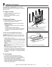
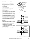
E. Install Outside Air Kit
• Keep duct runs short and straight to minimize restriction. A small dip is acceptable for a cold air trap.
• The outside air kit must be installed on the left hand side of the replace.
• Locate the air inlet in a clear area, preferably into prevailing wind during the heating season. Refer to Figure 5.2.
• Install as shown in Figures 7.3, 7.4 and 7.5.
• The air duct may be run vertically.
• The outside air inlet must be at least 3 ft (.91 m) below the top of the uppermost chimney section.
CAUTION! Risk of Fire or Asphyxiation! DO NOT draw outside combustion air from wall, oor or ceiling cavity, or
enclosed spaces such as an attic or garage.
• DO NOT place outside air inlet close to exhaust vents or chimneys. Fumes or odor could be drawn into the room
through the replace.
• Locate outside air inlet to prevent blockage from leaves, snow/ice, or other debris. Blockages could cause combus-
tion air starvation.
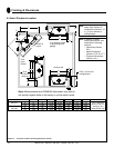
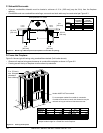
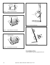
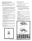
F. Junction Box Installation
NOTICE: Junction box should be installed during initial setup to avoid major reconstruction.
Your appliance is supplied with a junction box kit. We recommend the junction box be installed and wired at this time to
avoid reconstruction.
• The junction box kit is to be installed on the right side of the appliance; remove and discard the metal knockout.
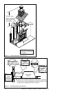
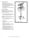
• Attach the junction box bracket to the junction box as shown in Figures 7.6 - 7.10.
• Bring the electrical wires to the inside of the junction box and secure in place with the Romex connector.
• Install the duplex receptacle in the junction box and attach the cover plate.
• Prior to attaching the junction box to the appliance, the heat shield supplied with your appliance must be installed. Insert
the top ange of the heat shield through the electrical knockout hole from the inside (Figure 7.9).
• Attach the junction box bracket to the side of the appliance. See Figure 7.10. Secure with the screws provided in the
fastener package.
Heat & Glo • EM-415, EM-485 • 33056 • Rev AF 7/12
•