


Heat & Glo • Cerona-36, Cerona-42 • 2106-900 Rev. A • 6/06
33
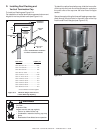
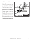
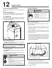
D. Junction Box Installation
If the box is being wired from the OUTSIDE of the
appliance:
• Loosen screw on the Romex connector, feed
the necessary length of wire through the
connector and tighten the screw.
• Make all necessary wire connections and
reattach the cover plate to the outer shell.
If the box is being wired from the INSIDE of the
appliance:
• Remove the screw attaching the junction box
to the outer shell, rotate the junction box
inward to disengage it from the outer shell (see
Figure 10.2).
• Loosen the screw on the Romex connector, feed
the necessary length of wire through the con-
nector and tighten the screw.
• Pull the electrical wires from outside the
appliance through this opening into the valve
compartment.
• Make all necessary wire connections to the
receptacle and assemble the receptacle and
cover to the junction box.
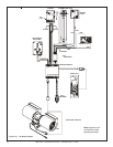
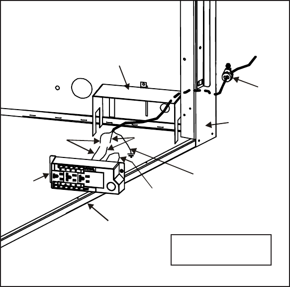
Figure 10.2 Junction Box Detail
NOTE: Do NOT wire
110VAC to wall switch.
WHITE
JUNCTION
BOX
STRAIN RELIEF
CONNECTOR
FRONT OF
FIREPLACE
COPPER GROUND
ATTACHED TO
GROUND
SCREW WITH
GROUND WIRE
HEAT SHIELD
BOTTOM PAN
GROUND WIRE
INSIDE BOX
BLACK
14/2WG