


Heat & Glo • Cerona-36, Cerona-42 • 2106-900 Rev. F • 04/08 39
12
12
Appliance Setup
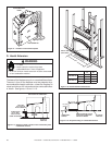
A. Remove Shipping Materials
Remove shipping materials from inside or underneath the
fi rebox.
B. Clean the Appliance
Clean/vacuum any sawdust that may have accumulated
inside the fi rebox or underneath in the control cavity.
C. Accessories
Install approved accessories per instructions included
with accessories. See Service Parts List for appropriate
accessories. Refer to Section 16.
Shock or fi re risk.
Use ONLY optional accessories approved for
this appliance.
• Using non-listed accessories voids warranty.
• Using non-listed accessories may result in a
safety hazard.
• Only Hearth & Home Technologies approved
accessories may be used safely.
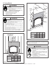
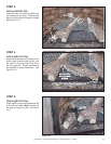
D. Ember Placement
Explosion Risk.
• Follow ember placement instructions in manual.
• Do NOT place embers directly over burner ports.
• Replace ember material annually.
Improperly placed embers interferes with proper burner
operation.
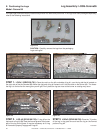
Placing the Ember Material
Ember material is shipped with this gas appliance. To place
the ember material:
• There are two types of ember shipped with the unit.
Embers for the burner surface and Mystic Embers for
the fl oor of the unit.
• Embers CANNOT be placed directly over ports. Care
should be taken not to cover the lighting trail of ports
(from back to front).
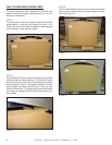
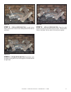
• When placing Glowing Embers
®
onto the burner care
should be taken so that the ports are not covered. Place
the dime-size ember pieces in front and behind of the
port trail, but not on or in between the ports (see Figure
12.2). Failure to follow procedure will likely cause lighting
and sooting problems.
Figure 12.2 Placement of Embers
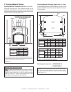
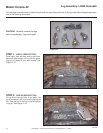
• Place Mystic Embers on areas of base refractory away
from port holes. Use this material to give the appliance
a realistic ash bed.
• Save the remaining ember materials for use during
appliance servicing. The embers provided should be
enough for 3 to 5 applications.
WARNING
WARNING
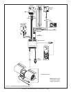
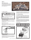
Figure 12.1
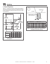
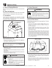
Heat-Zone/Heat-Duct Kits
• Remove the knockout from the sides of the appliance
and discard it (see Figure 12.1).
HEAT-ZONE/HEAT-DUCT
KNOCKOUT
• Heat-Zone: Determine the location for the air register/fan
housing assembly.
• Heat-Duct: Determine the location of the entry in the air
duct system.
• Reference the Heat-Zone/Heat-Duct Kit instructions for
the remaining installation steps.
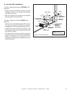
Note: Center the duct collar around the exposed hole and
attach it to the appliance with 3 screws BEFORE fi nal
positioning of the appliance.
EMBER PLACEMENT