


Heat & Glo • Cerona-36, Cerona-42 • 2106-900 Rev. F • 04/08 35
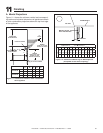
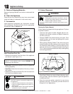
A. Mantel Projections
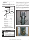
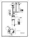
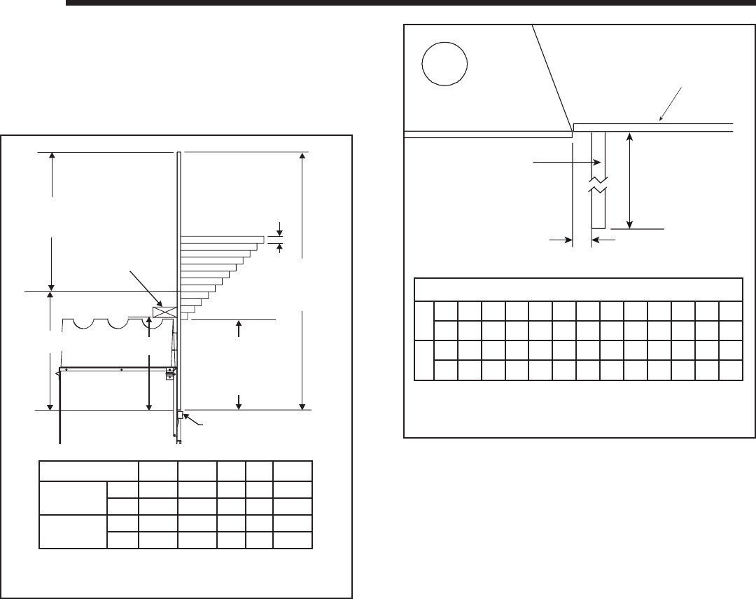
Figure 11.1 shows the minimum vertical and correspond-
ing maximum horizontal dimensions of appliance mantels
or other combustible projections above the top front edge
of the appliance.
11
11
Finishing
Figure 11.1 Clearances to mantels or other combustibles
above appliance
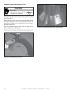
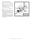
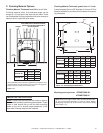
Figure 11.2 Clearances to Mantel Legs or Wall Projections
(Acceptable on both sides of opening.)
NON-COMBUSTIBLE
FACING MATERIAL
COMBUSTIBLE
FACING MATERIAL
1 in.
TYPICAL
D
MINIMUM
FROM TOP OF ARCH
OPENING TO FIRST
MANTEL PROJECTION
E
MINIMUM
FROM TOP OF ARCH
OPENING TO CEILING
FIREPLACE HEADER
1"
2"
3"
4"
5"
6"
7"
8"
9"
10"
11"
12"
TOP OF ARCH OPENING
CEILING
A
B
C
ABCDE
Cerona-36
in.
32-1/4 16-3/4 16 11 49
mm
819 425 406 279 1245
Cerona-42
in.
28-1/2 16-3/4 16 11 45-1/4
mm
724 425 406 279 1149
A
TOP VIEW
B
MANTEL LEG OR
WALL PROJECTIONS
INTERIOR WALL
If A minimum is _____, then B maximum is ______.
A
in.123456789101112
mm 25 51 76 102 127 152 178 203 229 254 279 305
B
in.123456789101112
mm 25 51 76 102 127 152 178 203 229 254 279 305