


4-00 17 30491D
BW36 SERIES WOODBURNING FIREPLACE
No one builds a better fire
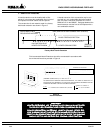
Figure 17
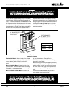
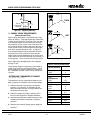
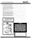
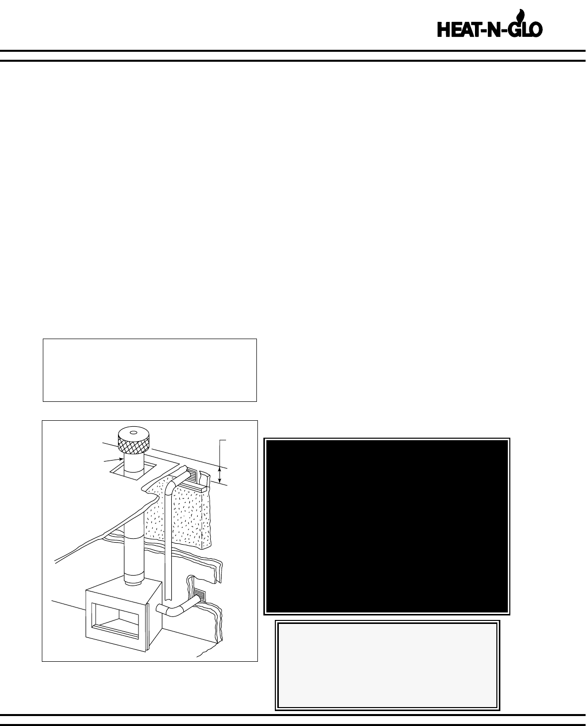
Outside Air Location
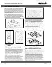
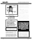
STEP 12 - Assembling the Chimney Sections.
Continue to add chimney sections through the roof
opening, maintaining at least a 2" air space.
STEP 13 - Installing Roof Flashing (optional).
If a roof flashing is to be used, install the roof flashing
appropriate to the roof pitch and install a TR344 ter-
minal cap (round) following the instructions shipped
with these accessories.
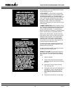
STEP 14 - Installing an Outside Combustion
Air Kit.
The outside air damper assembly is factory installed
on the left hand side of the firebox assembly. While
its use is optional, it is highly recommended to mini-
mize the effects of negative pressure within the
structure. Figure 17 illustrates two of many possible
methods that can be used to supply outside air to the
fireplace system. To complete the outside air system
install the AK22 Outside Air Kit according to the
installation instructions supplied with the compo-
nents.
UPPERMOST
CHIMNEY
SECTION
3' MIN.
NOTE: The outside air kit can terminate at
any level with the exception that it
must terminate at least three feet
below the chimney terminal cap as
shown in Figure 17.
CAUTION:
WHEN USING A GAS LOG SET, THE
FIREPLACE DAMPER MUST BE SET
IN THE FULLY OPEN POSITION.
THIS ENSURES A PROPER VENTING
OF COMBUSTION PRODUCTS.
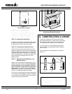
STEP 15 - Completion of the Fireplace Enclosure.
Complete the fireplace enclosure, allowing space for out-
side air ducts and gas piping if desired. Electrical wiring
should not come in contact with the unit. A minimum
clearance of 1" must be maintained between the fireplace
sides and the enclosure as well as the fireplace back and
the enclosure. See Figure 4 for framing details.
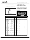
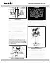
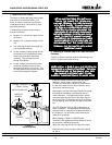
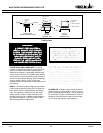
STEP 16 - Provisions for an Optional Gas Log Set.
Knockouts are provided on both sides of the fireplace to
allow for connection of a certified gas log lighter or a dec-
orative gas appliance with a maximum input of 100,000
BTU/hr. incorporating an automatic gas shutoff device
and complying with the Standard for Decorative Gas
Appliances for Installation in Vented Fireplaces, ANSI
Z21.60. The decorative gas appliance should be
installed in accordance with the National Fuel Gas Code,
ANSI Z223.1-1980. The side refractories are designed to
allow 1/2” black pipe to pass through. Use a non-com-
bustible sealant to seal any opening between the gas
pipe and refractory on the inside. Repack the insulation
removed, to seal around the gas pipe where it exits the
side of the fireplace. A minimum 1-1/2” air clearance
must be provided to the 1/2” black pipe. See Figure 18.
This fireplace has been set up for installation of the gas
pipe on the right hand side. If it is necessary to plumb
the unit from the left hand side, remove the gas cover
plate and gas tube from the right hand side of the unit
and install on the left hand side. Cover the hole in the
right hand side outer shell of the fireplace with the cover
plate that covered the gas tube.
WARNING!
THIS FIREPLACE WAS NOT TESTED BY THE
FIREPLACE MANUFACTURER FOR USE WITH AN
UNVENTED GAS LOG HEATER. DO NOT
INSTALL AN UNVENTED GAS LOG HEATER IN
THIS FIREPLACE UNLESS IT HAS BEEN SPECIFI-
CALLY TESTED AND LISTED BY UNDER-
WRITER’S LABORATORIES INC FOR USE IN THIS
SPECIFIC MODEL FIREPLACE. UNLESS THE
UNVENTED GAS LOG HEATER IS TESTED AND
LISTED FOR USE IN THIS FACTORY-BUILT FIRE-
PLACE, A FIRE HAZARD MAY BE CREATED
THAT CAN RESULT IN A STRUCTURE FIRE.