


Heat & Glo • 6000TR-OAK, 6000TR-OAK-IPI • 383-901 Rev. K • 5/0632
Step 10. Finishing
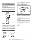
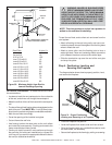
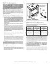
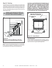
Figure 38 shows the minimum vertical and corresponding
maximum horizontal dimensions of fireplace mantels or other
combustible projections above the top front edge of the
fireplace. See Figures 2 and 3 for other fireplace clearances.
Only non-combustible materials may be used to cover the
black fireplace front.
WARNING: WHEN FINISHING THE FIREPLACE,
NEVER OBSTRUCT OR MODIFY THE AIR IN-
LET/OUTLET GRILLES IN ANY MANNER.
!
Figure 38.
Minimum Vertical and Maximum Horizontal
Dimensions of Combustibles above Fireplace
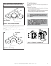
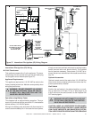
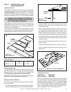
CAUTION: IF JOINTS BETWEEN THE FINISHED WALLS
AND THE FIREPLACE SURROUND (TOP AND SIDES)
ARE SEALED, A 300°
F. MINIMUM SEALANT MATE-
RIAL MUST BE USED. THESE JOINTS ARE NOT RE-
QUIRED TO BE SEALED. ONLY NON-COMBUSTIBLE
MATERIAL (USING 300° F. MINIMUM ADHESIVE, IF
NEEDED) CAN BE APPLIED AS FACING TO THE FIRE-
PLACE SURROUND. SEE THE DIAGRAM BELOW.
Hearth Extensions
A hearth extension may be desirable for aesthetic reasons.
However, ANSI or CAN/CGA testing standards do not require
hearth extensions for gas fireplace appliances.
Figure 39 Sealant Material
0”
FINISH WALL MATERIAL MAY BE
COMBUSTIBLE - TOP AND SIDES
0”
0”
NON-COMBUSTIBLE
BOARD
HIGH TEMPERATURE (300
0
F / 149
0
C MIN.)
TOP & SIDE SEAL JOINT
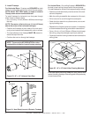
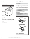
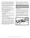
Note: There are 3 metal tabs holding the non-combustible
board in place for shipping. These tabs are to be cut off or
bent back before finishing around the fireplace front.
TOP FRONT EDGE OF FIREPLACE
1”
4”
9”
10”
11”
1”
2-1/2”
12”
13”
14”
15”
16”
17”
18”
31”
TO CEILING
9”
10”
11”
12”
8”
7”
6”
5”
4”
3”