


Heat & Glo • 6000TR-OAK, 6000TR-OAK-IPI • 383-901 Rev. K • 5/0628
Step 5.
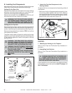
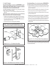
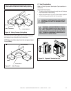
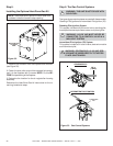
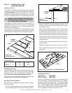
Installing the Optional Heat-Zone-Gas Kit
NOTE: There must be NO INSULATION or other com-
bustibles inside the framed firestop opening.
Figure 32.
1. Remove the knockout from the fireplace and discard it
(see Figure 32).
2. Center the duct collar around the exposed hole and at-
tach it to the fireplace with 3 screws. NOTE: Do this BE-
FORE final positioning of the fireplace.
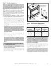
3. Determine the location for the air register/fan housing
assembly.
Reference the Heat-Zone-Gas kit instructions for the re-
maining installation steps.
!
!
!
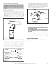
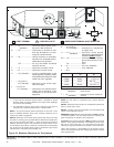
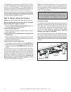
Step 6. The Gas Control Systems
WARNING: THIS UNIT IS NOT FOR USE WITH
SOLID FUEL.
Two types of gas control systems are used with these models:
Standing Pilot Ignition and Intermittent Pilot Ignition (IPI).
Standing Pilot Ignition System
This system includes millivolt control valve, standing pilot,
thermopile/thermocouple flame sensor, and piezo ignitor.
WARNING: 110-120 VAC MUST NEVER BE
CONNECTED TO A CONTROL VALVE IN A
MILLIVOLT SYSTEM.
Intermittent Pilot Ignition (IPI) System
This system includes a 3V control valve, electronic module
and intermittent pilot.
WARNING: CONTINUOUS 110-120 VAC SER-
VICE MUST BE WIRED DIRECTLY TO THE FIRE-
PLACE JUNCTION BOX.
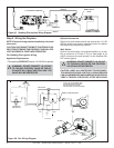
Figure 33. Gas Control Systems
INTERMITTENT PILOT IGNITION
STANDING PILOT
FLAME SENSOR
ROD
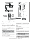
HEAT-ZONE-GAS
ATTACHES
HERE
3/8 in.
(10mm)