


Heat & Glo • 6000GLX-IPI-S/-R, 6000GLX-IPILP-S/-R • 2101-900 Rev. Q • 11/08 55
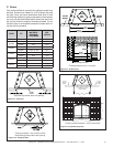
Figure 14.12 Top View
Figure 14.12 Top View
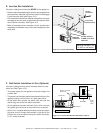
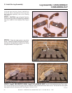
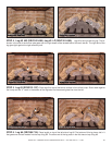
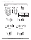
STEP 4. Log #2 NG (SRV2101-086): Log #2 LP (SRV2101-088): Log #2 is the right burning log. The air
shutter in the end of the burner tube goes over the right brass orifi ce located behind the main burner. The right end of the
log goes tight against the right refractory wall.
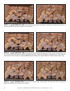
STEP 5. Log #3 (SRV2101-197): Place log #3 on top of the burner surface in front of the hump. Slide it back against
the hump and the “V” notch in the bottom of the log rests into the second grate tine from the left.
STEP 6. Log #4 (SRV386-716): Place log #4 on top of the left side of log #2. The bottom of this log has a slot in it
that goes over the tab molded into the top of log #2. The other end of the log rests in the fl at area on top of log #3.
Figure 14.14 Top View
Figure 14.14 Top View
Figure 14. 16 Top View
Figure 14. 16 Top View
2
2
3
3
4
4
2
2
3
3
4
4
Figure 14.13 Front View
Figure 14.13 Front View
Figure 14.11 Front View
Figure 14.11 Front View
Figure 14.15 Front View
Figure 14.15 Front View