


Heat & Glo • 6000GLX-IPI-S/-R, 6000GLX-IPILP-S/-R • 2101-900 Rev. Q • 11/08 53
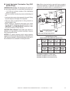
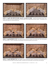
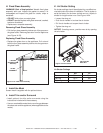
F. Ember Placement
WARNING! Risk of Explosion! Follow ember placement
instructions in manual. DO NOT place embers directly over
burner ports. Replace ember material annually. Improperly
placed embers interfere with proper burner operation.
Ember material is shipped with this gas appliance. To place
the ember material:
• Embers CANNOT be placed directly over ports. Care
should be taken not to cover the lighting trail of ports
(from back to front).
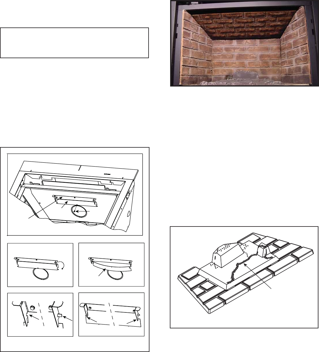
• Place dime-size pieces of Glowing Embers® just in front
of the port trail, but not on or in between the ports (see
Figure 14.6). Care should be taken so that the ports are
not covered. Failure to follow this procedure will likely
cause lighting and sooting problems.
Figure 14.6 Placement of Embers
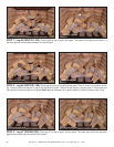
EMBER MATERIAL
• Place Mystic Embers on areas of base refractory away
from port holes. Use this material to give the appliance
a realistic ash bed.
• Save the remaining ember materials for use during
appliance servicing. The embers provided should be
enough for 3 to 5 applications.
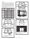
Figure 14.5
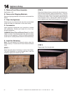
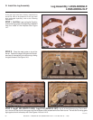
STEP 5.
Hold the top refractory with the brick pattern facing down.
Bring the back edge into the fi rebox slightly higher than the
front edge. Bring the back edge all the way to the metal
back wall of the fi replace. Raise the front edge up until it
clears the side refractory pieces. Drop the back edge down
and nest the sides and back into the groove around the
edges of the top piece of refractory.
Figure 14.4
DETAIL A.
BEND
Left
Right
Left
Right
Back Flap
Refractory
Standoff
Bracket
Screw
DETAIL B. DETAIL C.
DETAIL D.
DETAIL E.
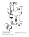
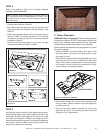
STEP 4.
Refer to the details in Figure 14.5 to position Optional
Refractory Standoff Bracket.
• Remove screw shown in Detail A.
• Bend down back fl ap along the two (2) perforations to
break back fl ap from refractory standoff bracket. See
Detail B.
• Rotate the separated piece and bend the back fl ap as
shown in Detail C to enable the tabs to fi t into the two
(2) holes on the left and right of the refractory standoffs
indicated in Detail D.
• Verify that the back fl ap rests on top of left and right
refractory standoff tabs noted in Detail E.
Note: If fi replace is rear vented and has no elbows in the vent
run, adjusting the refractory standoff bracket is allowed. If any
elbows are used in the vent run, DO NOT adjust the refractory
standoff bracket.