


Heat & Glo • 6000GLX-IPI-S/-R, 6000GLX-IPILP-S/-R • 2101-900 Rev. Q • 11/08 37
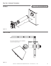
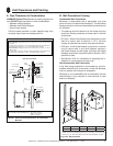
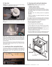
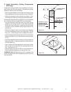
B. Rear Vent
NOTICE: Once appliance is set up for top or rear venting,
it CANNOT be changed at a later time.
Figure 9.6 Remove the insulation from the outer vent
pipe. For rear venting there is no insulation in the outer
vent pipe.
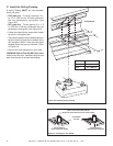
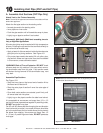
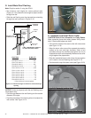
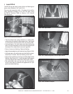
Figure 9.7 To attach the fi rst section of vent pipe, make
sure to use the fi berglass gasket in the manual bag to seal
between the fi rst vent component and the outer fi replace
wrap. Use 2 self tapping screws to secure the gasket to
the outer wrap.
Secure the fi rst section of venting to the fi replace by screw-
ing through the two straps left over from cutting the seal
cap strap in step 2.
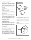
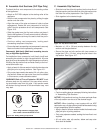
Figure 9.8 Non-combustible Board
C. Installing the Non-combustible Board
The factory supplied non-combustible board spans the
distance from the top of the fi replace to the center of
the framing header. This board must be used. See
Figure 9.8.
HEADER
HEADER
D. Securing and Leveling the Appliance
WARNING! Risk of Fire! Prevent contact with:
• Sagging or loose insulation
• Insulation backing or plastic
• Framing and other combustible materials
Block openings into the chase to prevent entry of blown-
in insulation. Make sure insulation and other materials
are secured.
DO NOT notch the framing around the appliance
standoffs.
Failure to maintain air space clearance may cause
overheating and fi re.
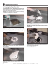
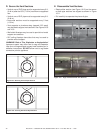
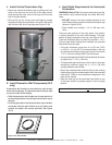
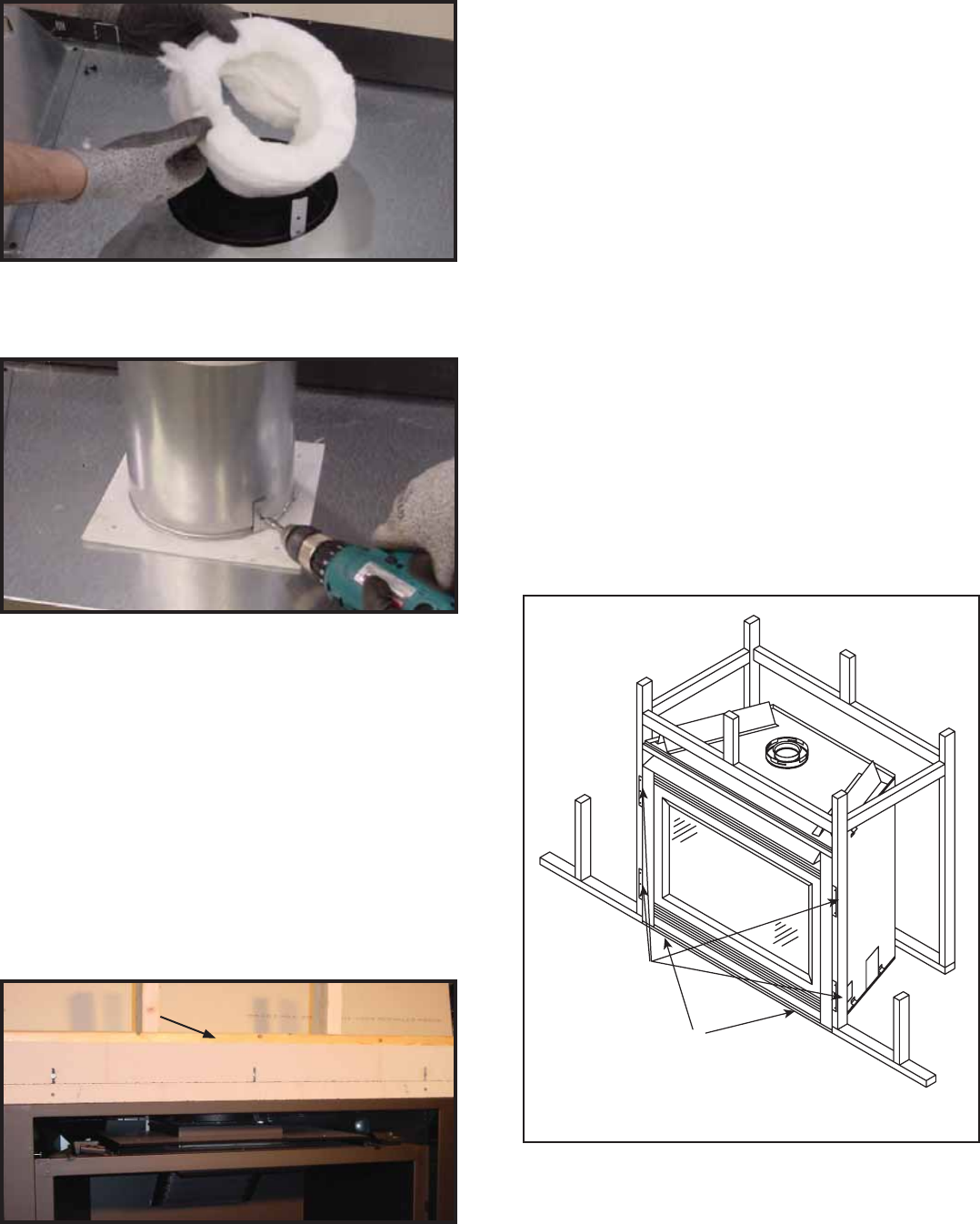
The diagram shows how to properly position and secure
the appliance (see Figure 9.9). Nailing tabs are provided
to secure the appliance to the framing members.
• Bend out nailing tabs on each side.
• Place the appliance into position.
• Keep nailing tabs fl ush with the framing.
• Level the appliance from side to side and front to back.
• Shim the appliance as necessary. It is acceptable to use
wood shims underneath the appliance.
• Secure the appliance to the framing by using nails or
screws through the nailing tabs.
• Secure the appliance to the fl oor by inserting two screws
through the pilot holes at the bottom of the appliance.
Figure 9.9 Proper Positioning and Securing of an Appliance
NAILING TABS
(BOTH SIDES)
PILOT HOLES