


26
Application, Operation, & Maintenance Manual DXM2 UNIT CONTROLS Heat Controller, Inc.
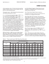
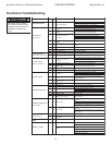
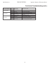
Symptom Htg Clg Possible Cause Solution
Insufficient Capacity/
X X Dirty filter Replace or clean
Not Cooling or Heating
Rduced or no air flow
Check for dirty air filter and clean or replace
Properly
in heating
Check fan motor operation and airflow restrictions
Too high of external static - check static vs blower table
Reduced or no air flow
Check for dirty air filter and clean or replace
in cooling
Check fan motor operation and airflow restrictions
Too high of external static - check static vs blower table
X X Leaky duct work
Check supply and return air temperatures at the unit and at
distant duct registers if significantly different, duct leaks
are present
X X Low refrigerant charge Check superheat and subcooling per chart
X X Restricted metering device Check superheat and subcooling per chart - replace
X Defective reversing valve Perform RV touch test
X X Thermostat improperly located Check location and for air drafts behind stat
X X Unit undersized
Recheck loads & sizing check sensible clg load and heat
pump capacity
X X Scaling in water heat exchanger Perform Scaling check and clean if necessary
X X Inlet water too hot or cold Check load, loop sizing, loop backfill, ground moisture
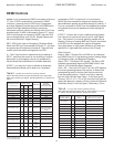
High Head Pressure
X
Reduced or no air flow
Check for dirty air filter and clean or replace
in heating
Check fan motor operation and airflow restrictions
Too high of external static - check static vs blower table
X Reduced or no water flow Check pump operation or valve operation/setting
in cooling
Check water flow adjust to proper flow rate
X Inlet water too hot Check load, loop sizing, loop backfill, ground moisture
X
Air temperature out of range in
heating
Bring return air temp within design parameters
X Scaling in water heat exchanger Perform Scaling check and clean if necessary
X X Unit overcharged Check superheat and subcooling - reweigh in charge
X X Non-condensables insystem Vacuum system and reweigh in charge
X X Restricted metering device Check superheat and subcooling per chart - replace
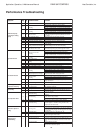
Low Suction Pressure
X
Reduced water flow
Check pump operation or water valve operation/setting
in heating
Plugged strainer or filter - clean or replace
Check water flow adjust to proper flow rate
X Water temperature out of range Bring water temp within design parameters
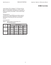
X
Reduced air flow
Check for dirty air filter and clean or replace
in cooling
Check fan motor operation and airflow restrictions
Too high of external static - check static vs blower table
X Air temperature out of range
Too much cold vent air - bring entering air temp within
design parameters
X X Insufficient charge Check for refrigerant leaks
Low Dischage Air
Temperature in Heating
X Too high of air flow Check fan motor speed selection and airflow chart
X Poor performance See “Insufficient Capacity”
High Humidity
X Too high of air flow Check fan motor speed selection and airflow chart
X Unit oversized
Recheck loads and sizing check sensible clg load and
heat pump capacity
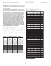
Only Compressor Runs
X X Thermostat wiring
Check G wiring at heat pump. Jumper G and R for fan
operation.
X X Fan motor relay
Jumper G and R for fan operation. Check for Line voltage
across blower relay contacts.
Check fan power enable relay operation (if present)
X X Fan motor Check for line voltage at motor. Check capacitor
X X Thermostat wiring
Check thermostat wiring at or DXM2. Put in Test Mode
and then jumper Y1 and W1 to R to give call for fan,
compressor and electric heat.
Unit Doesn't Operate in
Cooling
X Reversing Valve
Set for cooling demand and check 24VAC on RV coil.
If RV is stuck, run high pressure up by reducing water flow
and while operating engage and disengage RV coil voltage
to push valve.
X Thermostat setup
X Thermostat wiring
Check O wiring at heat pump. DXM2 requires call for
compressor to get RV coil “Click.”
X
X
Modulating Valve
Troubleshooting
X
Improper output setting
Verify the AO-2 jumper is in the 0-10V position
No valve operation
Check voltage to the valve
X
No valve output signal
Check DC voltage between AO2 and GND. Should be O
when valve is off and between 3.3v and 10v when valve
is on.
Replace valve if voltage and control signals are present at
the valve and it does not operate
For DXM2 check for “O” RV setup not “B”.
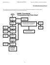
Performance Troubleshooting