


13
Heat Controller, Inc. DXM2 UNIT CONTROLS Application, Operation, & Maintenance Manual
to the compressor output. All other heat pump operating
modes will operate normally, and the accessory relay will
be off in all other operating modes.
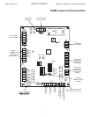
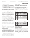
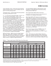
Thermostat Inputs – Table 5 shows the resulting demand
from differing combinations of inputs.
Y1 – Y1 is the input for compressor stage 1 if DIP1.3 = on.
Y1 is the input for Cooling Stage 1 if DIP1.3 = off.
Y2 – Y2 is the input for compressor stage 2 if DIP1.3 = on.
Y2 is the input for Cooling Stage 2 if DIP1.3 = off.
W – If Y1 and Y2 are active and DIP1.3 = on, then W is the
input for Heating Stage 3. If Y1 and Y2 are not active and
DIP1.3 = on, then W is the input for Emergency Heat. If
DIP1.3 = off, then W is the input for Heating Stage 1.
O – O is the input for Reversing Valve Relay if DIP1.3 =
on and DIP1.4 = on. O is the input for Heating Stage 2 if
DIP1.3 = off. O is the input for “Heat Mode” if DIP1.3 = on
and DIP1.4 = off; this means that the thermostat outputs a
“B” call when in Heating Mode and does NOT have an “O”
output. The DXM2 Control will employ “Smart RV” control.
This ensures that the RV will only switch positions if the
thermostat has called for a Heating/Cooling Mode change.
G – G is the input for Constant Fan Operation.
NSB and Override – NSB is the input for Night Setback
Mode. When Digital NSB is selected via the Accessory
Relays Dipswitch inputs and the NSB input is connected to
Ground “C”, then the appropriately confi gured Accessory
Relay is turned on to signal the digital thermostat to
go to Night Setback Setpoints. Stated differently, when
confi gured for Digital NSB Mode, the Accessory Relay
directly tracks the NSB input.
Note: Digital Night Setback feature requires a
compatible thermostat. Contact the manufacturer for
information on compatible thermostats.
When Digital NSB is NOT selected via the Accessory
Relays Dipswitch inputs and a communicating thermostat
confi gured for night setback is not connected, when the
NSB input is connected to Ground “C”, then Y1, Y2, W, O,
and G inputs are ignored. During this time period, if OVR is
momentarily connected to 24VAC, then Y1, Y2, W, O, and
G are once again monitored for 2 hours. After the 2 hour
override period, the DXM2 reverts back to ignoring Y1, Y2,
W1, O, and G, assuming the NSB input is still connected
to Ground “C”. There will be a random start timer when
coming back from NSB Mode.
Note: The maximum number of DXM2Controls with
daisy-chained “NSB” terminals is 75. Also, the
maximum total wire resistance of the “NSB” wiring is
500 Ohms.
OVR – OVR is the input for Night Setback Override or
Night Low Limit Staged Heating input (NLL). When Digital
NSB is NOT selected via the Accessory Relays Dipswitch
inputs and a communicating thermostat confi gured for night
DXM2 Controls
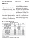
Table 4: Thermostat Inputs With Resulting Demands
1
Cooling input takes priority over dehumidifi cation input.
3
Above inputs assume DIP 1.3 is in the heat pump position, and DIP 1.4 is in the O position. When 1.3 is in the heat/cool position, Y1 & Y2 are used for
cooling inputs; W and O are used for heating inputs. When 1.4 is in the B position, the O column would be opposite logic.
4
N/A for single stage units; Full load operation for dual capacity units.
5
ON/OFF = Either ON or OFF; H/C = Either Heating or Cooling.
Thermostat Operating Modes
Mode
Input
3
Output
O G Y1 Y2
4
W H / DH RV Fan
1st stg
H/C
2nd stg
H/C
4
AUX Reheat
No Demand ON/OFF OFF OFF OFF OFF OFF ON/OFF OFF OFF OFF OFF OFF
Fan Only ON/OFF ON OFF OFF OFF OFF ON/OFF ON OFF OFF OFF OFF
Cooling 1st Stage ON ON ON OFF OFF OFF ON ON ON OFF OFF OFF
Cooling 2nd Stage ON ON ON ON OFF OFF ON ON ON ON OFF OFF
Cooling & Dehumidistat
1
ON ON ON ON/OFF OFF ON ON ON ON ON/OFF OFF OFF
Dehumidistat Only ON/OFF OFF OFF OFF OFF ON ON ON ON ON OFF ON
Heating 1st Stage OFF ON ON OFF OFF OFF OFF ON ON OFF OFF OFF
Heating 2nd Stage OFF ON ON ON OFF OFF OFF ON ON ON OFF OFF
Heating 3rd Stage OFF ON ON ON ON OFF OFF ON ON ON ON OFF