


18
Application, Operation, & Maintenance Manual DXM2 UNIT CONTROLS Heat Controller, Inc.
General Troubleshooting
Basic DXM2 board troubleshooting in general is best
summarized as simply verifying inputs and outputs.
After this process has been verifi ed, confi dence in board
operation is confi rmed and the trouble must be else where.
Below are some general guidelines required for developing
training materials and procedures when applying the DXM2
Control.
DXM2 Field Inputs
All conventional inputs are 24VAC from the thermostat and
can be verifi ed using a voltmeter between C and Y1, Y2,
W, O, and G.
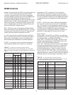
Sensor Inputs
All sensor inputs are ‘paired wires’ connecting each
component with the board. Therefore continuity on
pressure switches can be checked at the board connector.
The thermistor resistance should be measured with the
connector removed so that only the impedance of the
thermistor is measured. If desired, this reading can be
compared to the chart shown in the thermistor section
of this manual based upon the actual temperature of the
thermistor clip. An ice bath can be used to check calibration
of a thermistor if needed.
DXM2 Outputs
The compressor relay is 24VAC and can be verifi ed using
a voltmeter. The Alarm Relay can either be 24VAC as
shipped or dry contacts (measure continuity during fault)
for use with DDC by clipping the J4 jumper. Electric heat
outputs are 24VDC and require a voltmeter set for DC to
verify operation. When troubleshooting, measure from
24VDC terminal to EH1 or EH2 terminals.
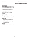
Test Mode
Test Mode can be entered for 20 minutes by pressing
the Test button. For Diagnostic ease at a conventional
thermostat, the Alarm Relay will also cycle during test
mode. The Alarm Relay will cycle on and off similar to the
Fault LED to indicate a code representing the last fault, at
the thermostat. Test Mode can also be entered and exited
by cycling the G input, 3 times within a 60 second time
period.
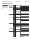
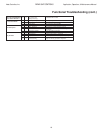
Basic Troubleshooting Information