


12
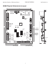
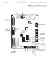
Application, Operation, & Maintenance Manual DXM2 UNIT CONTROLS Heat Controller, Inc.
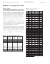
airfl ow for the current operating mode. For the fi rst
30 seconds of blower operation, the target airfl ow will
be 50% of the normal target airfl ow. For the next 90
seconds of blower operation, the target airfl ow will
be 75% of the normal target airfl ow. For Constant
Fan, Emergency Heat, and Test Mode operation, the
Soft Start Ramping profi le is bypassed, and the ECM
immediately ramps up to the normal target airfl ow.
c) Blower Off Delays – For ECM blower off delays, the
target airfl ow will be adjusted to 50% of normal target
airfl ow before the beginning of the blower off delay.
d) Default Blower Operation – If the DXM2 confi guration is
incorrect or incomplete with an ECM Blower connected,
the ECM will be operated using default target airfl ows
and operating parameters, and an ECM confi guration
fault will be active.
Hot Water Generator Operation – When the DXM2 is
confi gured to operate a hot water generator pump, the
pump will be directly controlled by the K2 relay, based
on the S3 dipswitch settings and the T5 (hot water
temperature) and T6 (compressor discharge temperature)
inputs. Hot water generator operating features include:
a) HWG operating setpoint selection (S3–3)
b) Temperature offset verifi cation for effi cient HWG
operation
c) HWG test mode (S3–2)
Proportional Valve Operation – When the DXM2 is
confi gured to operate a proportional valve (optional),
the valve will be directly controlled by the DXM2. For
controlling the proportional valve, the DXM2 monitors the
entering water temperature and leaving water temperature.
The valve is controlled in the following way:
a) Maintain the appropriate temperature difference across
the water coil (EWT–LWT for heating, LWT–EWT for
cooling).
b) Maintain the leaving water temperature below the
appropriate Maximum Heating LWT and above the
Minimum Cooling LWT limits.
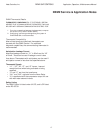
SPECIAL DXM2 APPLICATION NOTES / ACCESSORY
RELAYS
Generally the following applications are based upon
confi guring the accessory relays.
Cycle with Fan – If Accessory relay 1 is confi gured to
“cycle with fan”, Accessory relay 1 will be on any time the
Fan Enable relay, or ECM Blower is on.
Cycle with Compressor – If Accessory relay 2 is
confi gured to “cycle with compressor”, Accessory relay 2
will be on any time the Compressor relay is on.
Digital Night Setback – If an Accessory relay is confi gured
for Digital NSB, the Accessory relay will be on any time the
NSB input is connected to Ground “C”.
Note: If there are no Accessory relays confi gured
for Digital NSB, and the DXM2 is not connected
to a communicating thermostat confi gured for
night setback, then the NSB and OVR inputs are
automatically confi gured for “mechanical” operation.
See Mechanical NSB operation below.
Note: Digital Night Setback feature requires a
compatible thermostat. Contact the manufacturer for
information on compatible thermostats.
Mechanical Night Setback – When the NSB input is
connected to Ground “C”, all thermostat inputs (G, Y1,
Y2, W, and O) are ignored. A thermostat setback Heating
call can then be connected to the OVR input. If the OVR
input becomes active, then the DXM2will enter NLL Staged
Heating Mode. NLL Staged Heating Mode would then
provide heating during the NSB period.
Water Valve/Slow Opening
– If an Accessory relay is
confi gured for Water Valve/Slow Opening, the Accessory
relay will turn on 60 seconds prior to the Compressor Relay
turning on.
Outside Air Damper – If an Accessory relay is confi gured
for OAD, the Accessory relay will normally turn on any
time the Fan Enable relay is on. But, following a return
from NSB (NSB input no longer connected to Ground “C”)
to Normal Mode, the Accessory Relay will not turn on for
30 minutes even if the Fan Enable Relay is on. After this
30-minute timer expires, the Accessory Relay will turn on if
the Fan Enable Relay is on.
Humidifi er – If Accessory relay 2 is confi gured for a
Humidifi er, the Accessory relay will be on any time the H
input is active.
Hydronic Economizer – If Accessory relay 1 is confi gured
to be used as a hydronic economizer, normal cooling
operation will be modifi ed.
If Accessory relay 1 is confi gured as a single stage
hydronic economizer, when a fi rst stage cooling demand is
present and the H input is active, the accessory relay will
be activated instead of the compressor output. All other
heat pump operating modes will operate normally, and the
accessory relay will be off in all other operating modes.
If Accessory relay 1 is confi gured as a hydronic economizer
for both stages, when a fi rst stage cooling demand is
present and the H input is active, the accessory relay will
be activated instead of the compressor output. When a
second stage cooling demand is present with the H input
active, the accessory relay will be activated in addition
DXM2 Controls