


August 1, 2008
Page 29
Heat & Glo · Tiara I B & Tiara II B · 7010-149M
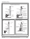
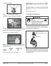
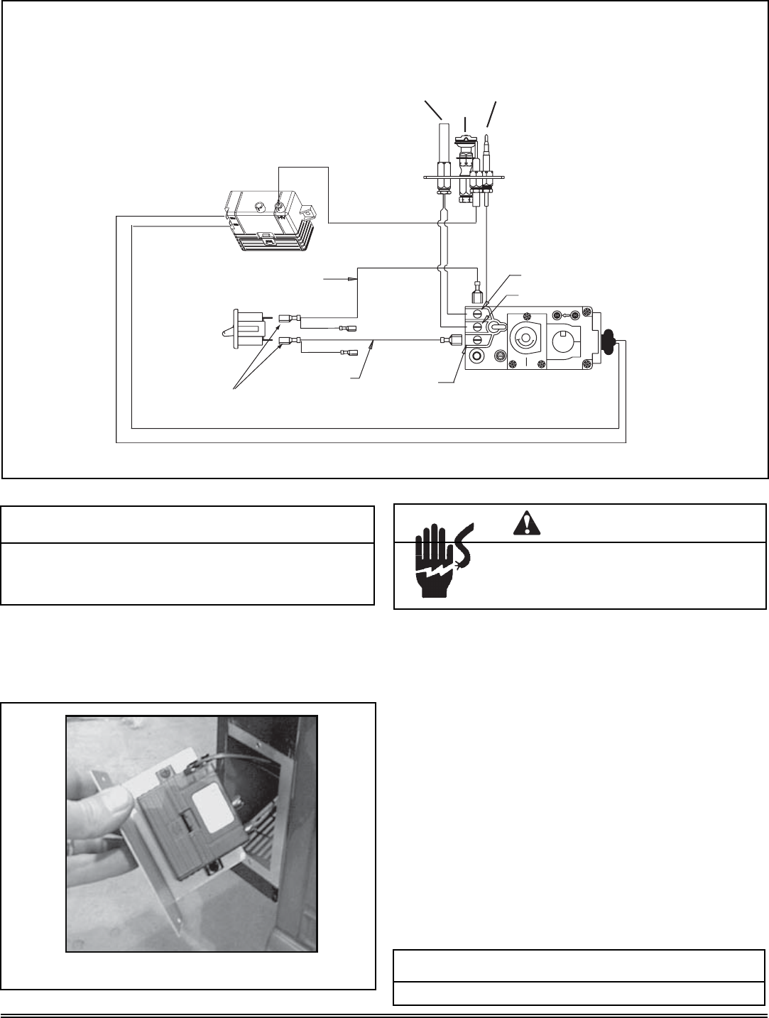
Figure 7.1
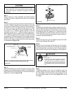
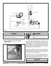
Shock hazard.
• Replace damaged wire with type 105
O
C
rated wire.
• Wire must have high temperature insulation.
CAUTION
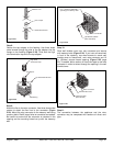
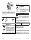
Figure 7.2
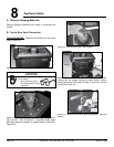
D. Ignition Module Access and Battery
Replacement
CAUTION
Label all wires prior to disconnection when servicing controls.
Wiring errors can cause improper and dangerous operation.
Verify proper operation after servicing.
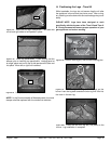
The Ignition Module (automatic-ignitor) is located on the
side of the appliance. This module was incorporated into the
design of the Tiara I-B & II-B to facilitate "one hand" lighting
of the appliance. When the gas control knob is turned to
the "Pilot" position, and depressed, the ignitor should begin
sparking immediately. If the ignitor does not begin sparking
immediately, then it is in need of service.
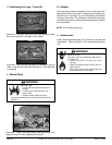
The ignitor is located on a plate attached to the side of the
appliance using two #8 Phillips head screws. To access the
ignitor, remove the two screws securing the plate to the side
of the appliance and slide the plate out.
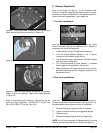
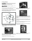
The single "AA" 1.5 V battery that powers the ignitor is
located in the module. To replace the battery, open the
battery compartment and remove old battery. Replace the
battery. Make sure the polarity is correct.
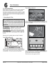
O
F
F
P
I
L
O
T
O
N
TP
TH
TPTH
LO
HI
EA
P
I
L
O
T
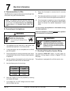
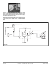
IGNITON MODULE
ON / OFF SWITCH
REMOTE SWITCH
BLACK
BLACK
VALVE
TH
TP
TPTH
PILOT ASSEMBLY
THERMOPILE
GAS PILOT IGNITER
THERMOCOUPLE
CAUTION
Battery polarity must be correct or module damage will occur.