


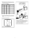
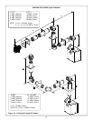


20
2. Continue Adding Vent Components
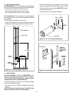
WARNING: INSTALLATION OF THIS FIRE-
PLACE REQUIRES THE USE OF A HEAT
SHIELD ABOVE THE FIRST 90
0
ELBOW IN THE
VENTING SYSTEM.
Figure 19
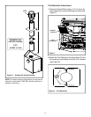
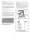
To Install the Heat Shield:
1. Determine if the heat shield is required. Do so by mea-
suring the vertical distance between the top horizontal
surface of the elbow to any combustible surface above.
If the distance is more than 4 inches, the heat shield is
NOT required. If it is 4 inches or less, the heat shield IS
REQUIRED. Install per the following steps. See Figure 19.
!
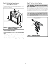
• Continue adding vent components, locking each succeed-
ing component into place.
• Ensure that each succeeding vent component is secure-
ly fitted and locked into the preceding component in the
vent system.
• 90° elbows may be installed and rotated to any point
around the preceding component’s vertical axis. If an el-
bow does not end up in a locked position with the pre-
ceding component, attach with a minimum of two (2)
sheet metal screws.
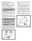
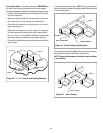
Figure 20
CORRECT INCORRECT
2. Fasten the shield in place using the pilot holes provided
in the part. The shield should be oriented such that the
13 1/8 inch dimension (longest dimension) is running in
the same direction the elbow is pointing. The shield should
be centered directly above the elbow, and positioned so
that it creates a 1/2 inch airspace between the shield
and the combustible surface. See Figure 20.
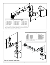
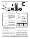
Figure 22. Adding Venting Components
!
If the installation is for a termination cap attached directly
to the fireplace, skip to the sections, Install Firestops and
Vent Termination.
!
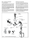
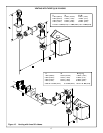
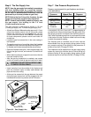
WARNING: ENSURE THAT THE FIBERGLASS
GASKET SUPPLIED WITH THE FIREPLACE
SEALS BETWEEN THE FIRST VENT COMPONENT
AND THE OUTER FIREPLACE WRAP.
WARNING: A 3/8 INCH (9.5 MM) BEAD OF
STOVE CEMENT MUST BE PLACED AROUND
THE 5 INCH (127 MM) FIREPLACE STARTING COL-
LAR BEFORE ATTACHING THE FIRST VENT COM-
PONENT. FAILURE TO SEAL THIS JOINT MAY
CAUSE THE FIREPLACE TO OPERATE IMPROPER-
LY. SEE THE DIAGRAM .
Figure 21.
3”
(76mm)
SCREW