


Heat & Glo • Escape-42DV • 2052-900 Rev. R • 10/0830
A. Recommendation for Wire
This appliance requires 110-120 VAC be wired to the
factory installed junction box.
10
10
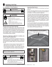
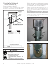
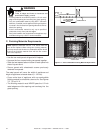
Electrical Information
NOTE: This appliance must be electrically wired and grounded
in accordance with local codes or, in the absence of local
codes, with National Electric Code ANSI/NFPA 70-latest
edition or the Canadian Electric Code, CSA C221.1.
B. Connecting to the Appliance
Wire 110V to electrical junction box.
Do NOT wire 110V to valve.
Do NOT wire 110V to wall switch.
• Incorrect wiring will damage millivolt valves.
• Incorrect wiring will override IPI safety lockout
and may cause explosion.
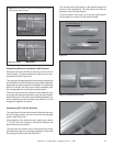
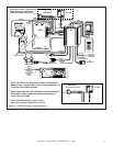
C. Intellifi re Ignition System Wiring
This appliance requires a 110 VAC supply to the appliance
junction box for operation. A wiring diagram is shown in
Figure 10.2.
This appliance is equipped with an Intellifi re control valve
which operates on a 3 volt system.
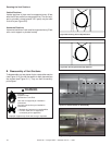
This appliance is supplied with a battery pack and a 3 volt
AC transformer, which requires the installation of the sup-
plied junction box. It is highly recommended that the junc-
tion box be installed at this time to avoid reconstruction.
The battery pack requires two D cell batteries (not includ-
ed). Batteries cannot be placed in the battery pack while
using the 3 volt transformer. Batteries shouldn’t be placed
into the holder until needed. The higher temperatures will
shorten their life.
CAUTION
Battery polarity must be correct or module damage will
occur.
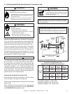
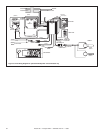
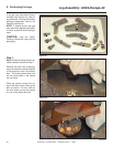
Optional Accessories Requirements
Wiring for optional accessories should be done now to
avoid reconstruction.
WARNING
This appliance comes standard with a multi-function
wall switch installed in the unit. A bag containing the wall
switch, cover plate and fl ame control solenoid is located
in the manual bag assembly on the right side of the unit.
Follow the “Determine Location” and “Wiring the Wall
Switch” sections of the WSK-MLT instructions.
Install the fl ame control solenoid by following Steps 5 - 11
in the “Installing the Control Box” section of the WSK-MLT
instructions.
Also carefully follow the “Setting Flame Height/Manifold
Pressure” section of the included instructions to properly
set the valve pressure. Operating instructions are also in-
cluded in the WSK-MLT instructions.
CAUTION
Remove refractory panels and mesh when operating
appliance using the battery pack or damage to components
may occur.
Use battery pack to operate appliance only in a power failure
situation.
• A 110-120 VAC circuit for this product must be protected
with ground-fault circuit-interrupter protection, in
compliance with the applicable electrical codes, when
it is installed in locations such as in bathrooms or near
sinks.